Operation, Operation, cont’d, Front panel features – Extron Electronics SCP 100P User Guide User Manual
Page 8
SCP 100P • Operation
SCP 100P • Operation
Operation, cont’d
Display Power button and LED
— Once the System 5cr Plus has
been programmed with the commands for the specific
projector, pressing this button toggles the projector’s power
on or off.
The LED lights when projector power is on. The LED
blinks quickly during projector power-up, and it blinks
slowly during projector power-down. While the LED is
blinking, do not send commands to the projector because
the projector is not able to accept them. The blinking
periods (power-up/down delay time) are generated within
the System 5cr Plus, not the projector. The blinking periods
can be set only via the Windows-based control program.
Display Mute button
— Press this button to toggle the
projector’s video “mute” function (to turn off/on the
displayed image) once the Mute button has been
programmed for use with the projector.
Display Mode button
— This button can be programmed to
switch the mode of the projector between computer-video
(RGB), S-video, and composite video. It replicates the 1-
button (step) mode function provided on some projectors’
remote controls.
3
IR remote window
— This windows corresponds to the IR
receiver port on the System 5cr Plus switcher. It is used for
receiving commands from the IR 401 remote control (from a
distance of up to 30 feet ((9.1 m)) away) and sending them to the
switcher. Infrared signals from other devices are not passed on
to the IR Emitter or the IR Broadcaster.
Audio adjustment control and LEDs
4
Audio indicator LEDs (Max, Clip, and Min)
— These LEDs
light in response to changes made via the front panel volume
control knob or RS-232 or control software commands.
Max LED
(red) – This LED lights when the volume control knob
has reached its maximum limit. It does not indicate the
audio level.
Clip LED
(green) – This LED lights when the audio output level
starts to peak (overdrive) and the signal is clipped, often
when the input level is too high. It is used during audio
input attenuation setup.
Min LED
(red) – This LED lights when the volume control knob
has reached its minimum limit. It does not indicate the
audio level.
2-3
The SCP 100P replicates the front panel controls of the
System 5cr Plus.
The System 5
cr
Plus cannot be configured from the
SCP 100P control pad. All switcher setup must be done
from the switcher’s front panel or via RS-232 control.
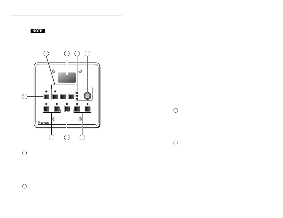
Front Panel Features
SCP 100P
PC1
ROOM
POWER
MUTE
MODE
IR REMOTE
VOLUME
MAX.
MIN.
CLIP
PC2
INPUT 3
VID1
VID2
DISPLAY
AUDIO
2
7
3
4
5
6
8
1
System control features
1
Room button and LED
— This allows control of “room”
functions – items such as room lighting, window coverings, and
display screens – via momentary or latching contact through the
Relay port. These contacts can be used to control any equip-
ment as long as the contacts do not exceed a total of 24 volts at
1 ampere. The LED lights while the room function is active (on).
Refer to the System 5
cr
Plus User’s Manual for information on the
room function/Relay port.
2
Display function controls and LED
— The settings of the
display functions (power, mute, and mode) are customized for
each projector. These buttons function only after they have been
programmed, either by “learning” IR commands or by loading
projector commands (drivers) from the Extron IR library.
Operation
2-2