Introduction and installation, cont’d, Po wer mute, Mode volumn – Extron Electronics SCP 100P User Guide User Manual
Page 6: Mounting the scp to the wall box, Pre-installation testing/troubleshooting, Rear panel (circuit board) and cabling
SCP 100P • Introduction and Installation
SCP 100P • Introduction and Installation
Introduction and Installation, cont’d
SCP 100P, and watching the LEDs on the switcher to see if the
system switches to the desired inputs.
The connections between the SCP 100P and the
System 5
cr
Plus can be tested even if input/output
devices are not available.
Mounting the SCP to the wall box
Once the system has been cabled and tested, the control pad can
be installed in the wall or furniture.
1.
With power removed, insert the SCP 100P into the wall or
furniture.
2.
Mount it to the wall box (or mounting brackets) with the
provided machine screws (as
shown in the illustration below),
or attach it directly to the
furniture with wood or
metal screws.
1-5
PO
WER
MUTE
DISP
LA
Y
SCP
-100
MODE
VOLUMN
AUD
IO
RO
OM
MIN.
UNITY
MAX.
PC1
PC2
PC3
VID1
VID2
1
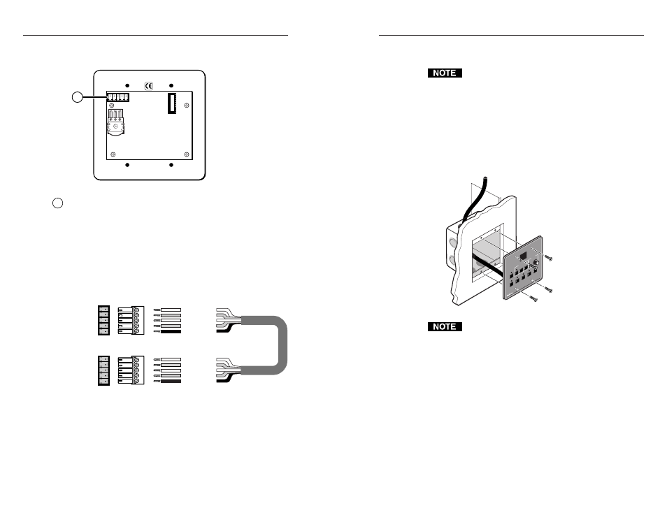
Rear panel port
— Connect this 3.5 mm, 5-pole captive screw
port to either one of the System 5cr Plus’s Aux port 5-pole
captive screw connectors. Captive screw connectors are
included with the SCP 100P. The cable is not supplied. See
page A-2 for a list of recommended cables. The cable should be
a maximum of 300 feet (91.4 meters) long.
The System 5cr Plus’s Aux 1 and Aux 2 ports provide a total of
500 mA, split between the two ports, so each port provides
250 mA of current for powering the control pad.
1.
Wire the connectors as shown below.
IR signals in
Gnd
Gnd
+12V
System 5
AUX port
A
B
C
D
E
IR signals in
Gnd
Comm signal
Comm signal
Gnd
+12V
Port on
SCP
circuit
board
2.
Plug one end of the cable into the SCP 100P rear panel port
first, and then plug the other end into one of the
System 5cr Plus Aux ports.
Pre-installation testing/troubleshooting
Before installing the control pad into the wall or furniture, test
the system to make sure that the connections are correct and the
SCP is working correctly. Test the system by powering on the
switcher, then pressing the input selection buttons on the
Rear panel (circuit board) and cabling
1
1-4
If you are not installing the SCP into a grounded metal
wall box, make sure that the faceplate is grounded to an
earth ground.