Extron Electronics VTG 400D_400 DVI Setup Guide User Manual
Installation, Step 1 — connect video outputs, Step 2 — connect audio outputs
Setup Guide — VTG 400D/400 DVI
1
This guide provides basic instructions for an experienced
installer to set up and operate the Extron VTG 400D/
VTG 400 DVI
Installation
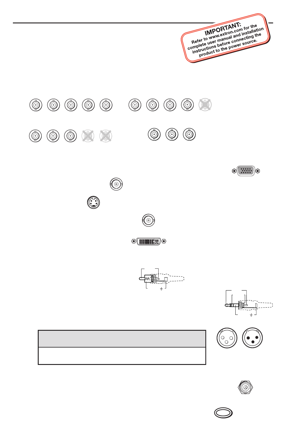
Step 1 — Connect video outputs
Attach output devices to the VTG.
For RGBHV, RGBS, or RsGsBs output:
N
The 15-pin HD RGB output connector outputs RGBHV, RGBS, RGsB,
and RsGsBs.
For composite video output:
For S-video output:
For SDI/HDSDI output (VTG 400D only):
For DVI output (VTG 400 DVI only):
Step 2 — Connect audio outputs
Attach audio output devices to the VTG. Wire the connectors as shown below.
RCA (unbalanced mono audio) output 1:
3.5 mm mini phone jack (unbalanced mono left and right channels) output 2:
XLR (balanced mono) output 3:
Step 3 — Connect scope trigger
When using an oscilloscope, connect the scope’s external trigger to the trigger
connector of the VTG.
Step 4 — Power up
Power up the VTG by holding down the Power button for 1 second.
Continue on the next page for operation instructions.
RGBHV output
RGBS output
R
G
B
V
H
/HV
R
G
B
V
H
/HV
R
G
B
V
H
/HV
RGsB, RsGsBs output
Component video output
(R-Y, Y, B-Y)
R-Y
Y
B-Y
RGB
COMPOSITE
S-VIDEO
SDI/HDSDI
DVI-D
Tip (+)
Sleeve ( )
Audio Plugs.eps
RCA Connector
Sleeve ( )
Ring (R)
Tip (L)
Application
Pin 1
Pin 2
Pin 3
Balanced audio (std.)
gnd (shield)
positive (+)
negative (-)
(on sending/female connector) (hot/live)
(cold/return)
3-pin XLR Pin Configuration
TRIGGER
3-pin
Male
3
2
3
1
3-pin
Female
3
2
3
1
POWER