Extron Electronics RGB 202xi VTG User Guide User Manual
Page 8
RGB 202 Rxxxxxiiiii, RGB 202 Rxxxxxiiiii VTG • Installation and Operation
RGB 202 Rxxxxxiiiii, RGB 202 Rxxxxxiiiii VTG • Installation and Operation
Installation and Operation, cont’d
RGB 202
VTG
BO
OST
LEVE
L
CO
NT
RO
L
PEA
K
INP
UT
1
2
W
ITH A
DS
P
TM
MIN
I VT
G
CEN
TE
RIN
G
Rxi
SX
GA
SV
GA
VG
A
20
2
VTG
XG
A
2-5
2-4
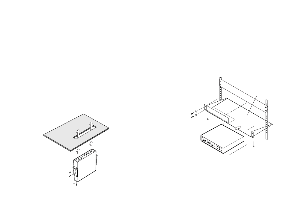
Through-desk mounting
1
.
If rubber feet were installed on the interface, remove them.
2
.
Insert the machine screws (provided in the mounting kit)
through the slots in the optional through-desk mounting
brackets (part #70-077-02), and loosely attach the brackets
to the interface.
3
.
Hold the interface with attached brackets against the
underside of the desk/table. With a soft pencil mark the
location of holes for screws on the desk. Mark the
opening, approximately 1.8” x 8.9” ( 4.6 cm x 22.6 cm).
4
.
Cut out the material from the installation area with a
jigsaw. Check the opening size by inserting the interface
part way through the hole. If needed, use a saw, file or
sandpaper to enlarge the hole. Smooth the edges of the
hole with sandpaper.
5
.
Drill 1/4” (6.4 mm) deep, 3/32” (2.38 mm) diameter pilot
holes in the desk or table at the marked screw locations.
The holes should be drilled from the underside or inside
(concealed side) of the furniture, where the interface will
be located.
6
.
Attach the interface to the desk with the provided wood
screws, as shown in
this illustration.
Through-desk mounting
7
.
To adjust the height of the interface within the desk, slide
the interface up or down to the desired position, then
tighten the screws that attach the brackets to the interface.
Rack mounting
1
.
If feet were installed on the bottom of the interface, remove
them.
2
.
Place the interface on one half of the 1U (one unit high,
19” wide) optional rack shelf (part #60-190-01). Align the
front of the interface with the front of the shelf, and align
the threaded holes on the bottom of the interface with the
holes in the rack shelf.
3
.
Attach the interface to the rack shelf with the two provided
4-40 x 1/8” machine screws. Insert the screws from the
underside of the shelf, and securely fasten them through
diagonally opposite corners as shown in the illustration
below.
(2) 4-40 x 1/8" screws
Use 2 mounting holes on
opposite corners
False front panel
uses 2 front holes
RGB
202 R
VTG
BO
OST
LEV
EL
CO
NTR
OL
PEA
K
INP
UT
1
2
W
ITH
AD
SP
TM
MIN
I V
TG
CEN
TER
ING
xi
SXG
A
SV
GA
VG
A
202
VT
G
XG
A
Rack mounting
4
.
Attach the false front panel (provided with the rack shelf)
to the unoccupied side of the rack (as shown above), or
install a second half-rack-width device in that side by
repeating steps 1 – 3.
5
.
Attach the rack shelf to the rack using four 10-32 x ¾” bolts.
Insert the bolts through #10 beveled washers, then through
the holes in the rack ears and rack, as shown above.