Installation and operation, cont’d, Mounting the rgb 340, Front and rear panel features – Extron Electronics RGB 340 User Manual
Page 8
RGB 324/326/340 • Installation and Operation
RGB 324/326/340 • Installation and Operation
Installation and Operation, cont’d
2-5
2-4
Extron
RGB 324
INPUT
HIGH Z
75 Ohm
H. SHIFT
V. SHIFT
VIDEO LEVEL
AUDIO LEVEL
ADJUST
SHOW ME/
SELECT
AUDIO
1
7
5
6
2
4
3
Extron
RGB 326
INPUT
HIGH Z
75 Ohm
ACTIVE
AUDIO
1
8
2
4
3
ANALOG
AUDIO
H SHIFT
SHOW ME/
SELECT
HI-Z
75
V SHIFT
VIDEO LEVEL
ADJUST
RGB 340
AUDIO LEVEL
INPUTS
1
2
4
3
6
5
7
Tip (L)
Sleeve (GND)
Tip (L)
Ring (R)
Sleeve (GND)
8.
Set the rear panel peaking jumpers, and cable and test the
buffer before fastening the buffer into the wall box. The
jumpers and cables will be inaccessible after installation
.
See “Rear panel/circuit board features and jumpers” and
“Cabling” in this chapter for details.
Mounting the RGB 340
You may need to install the cables into the wall, furniture, or
conduits before installing the buffer. A drawing showing
dimensions is provided in appendix B.
1.
Hold the buffer against the underside of the desk or other
furniture. Mark the location of holes for screws on the
furniture.
2.
From the side of the furniture where the interface will be
located, drill 1/4” (6.5 mm) deep, 3/32” (2.4 mm) diameter
pilot holes in the furniture at the marked screw locations.
3.
Insert and loosely fasten four wood screws into the pilot
holes, leaving only 1/4” of the screw protruding.
4.
Set the internal peaking jumpers and attach the cables to
the rear panel. The jumpers and cables will be inaccessible
after installation
. See “Rear panel/circuit board features
and jumpers” and “Cabling” in this chapter for details.
5.
Align the screws with the slots in the buffer’s mounting
ears, and place the buffer against the surface (with the
screws through the mounting ear slots).
Mounting the RGB 340
6.
Slide the buffer slightly forward or backward, then tighten
all four screws to fasten it into place.
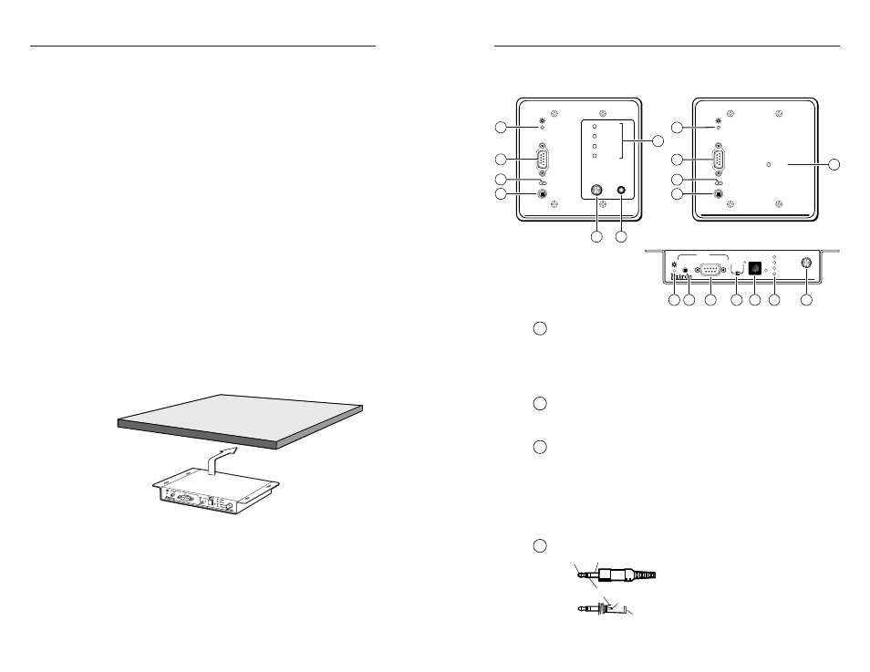
Front and rear panel features
Front panel features and operation
1
Power LED
— The power LED:
•
Lights steadily to indicate that the buffer is receiving power.
•
Blinks when the RGB 320 is busy, indicating that the Show
Me/select button must be pressed a second time to send
the request to display that buffer’s input (RGB 324/340).
2
Input 9-pin D male connector
— This port accepts analog
RGBHV, RGBS, RGsB, and RsGsBs computer video signals via a
monitor breakout cable (MBC) or laptop breakout cable (LBC).
3
High Z/75 ohm switch
— Select the video termination
impedance that provides the best picture.
•
Set this switch to High Z (high impedance) if a local
monitor is connected, a laptop breakout cable is used, or if
the picture is too dark (double-terminated).
•
Set this switch to 75 ohms if no local monitor is connected
or if the picture is too bright or blooming (unterminated).
4
Audio input jack
— This 3.5 mm female stereo jack is for left
and right unbalanced stereo audio
input. Wire the connector as
shown at left.