Installation and operation, cont’d, Rear panel/circuit board features and jumpers, Red blue green – Extron Electronics RGB 340 User Manual
Page 10
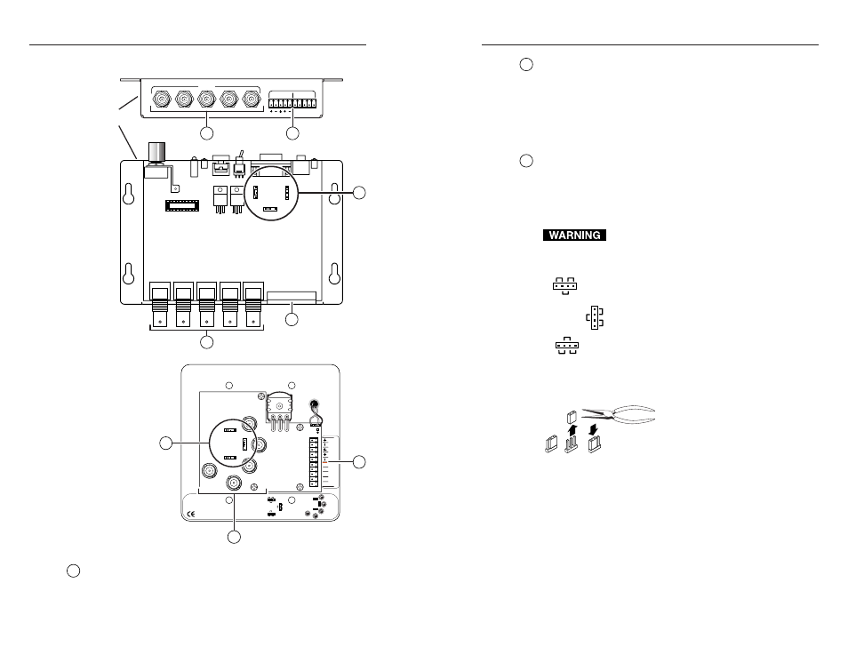
RGB 324/326/340 • Installation and Operation
RGB 324/326/340 • Installation and Operation
Installation and Operation, cont’d
Rear panel/circuit board features and jumpers
RGB 324/326
RGB 340
J1
0
J8
J9
J1
0
J8
J9
.8V
.9V
.8V
.9V
.7V
.7V
.7V
.8V
.9V
RGB 324, RGB 326
Interface Buffers
Level/Peaking
jumpers
Default =
0.7V (jumper
in the middle
position)
BLUE
RED
GREEN
VSYNC
HSYNC
33-320-01, Rev. C 07 00
BLUE
RED
GREEN
VSYNC
HSYNC
J1
0
J8
J9
J10
J8
J9
C
O
M
/ P
WR
Audio
33-321-01, Rev. A
A
L
R
BC
D
E
COM/PWR
L AUDIO R
OUTPUT
R
G
B
H
V
A B C D E
1
2
1
2
1
2
3
3
J1
0
J8
J9
.8V
.9V
.8V
.9V
.7V
.7V
.7V
.8V
.9V
RED
BLUE
GREEN
1
Video output BNC connectors
— Connect coaxial cables to
these connectors for RGBHV, RGBS, RGsB, or RsGsBs analog
video output. For composite sync (RGBS) signals, connect the
sync cable to the BNC connector labeled V or VSYNC.
2
Audio output and communications/power connector
—
Wire this 3.5 mm 10-pole captive screw connector as shown in
“Connecting the buffer to the RGB 320 with installation cable”
in this chapter (pages 2-11 to 2-14).
The left half of this connector is for audio output to the RGB 320.
The right half of this connector serves as a port for power and
buffer-RGB 320 communications.
3
Level/peaking jumpers
— Changes to video peaking may be
needed for high resolution signals or to compensate for signal
loss from long cable runs. The buffers have separate jumpers
for red, green, and blue video signals. See the diagram shown
here or on the product label, and, for the RGB 340, also see
“Opening the RGB 340 enclosure for jumper adjustment” below.
Changes to internal jumper settings must be
performed by authorized service personnel only.
• 0.7V – This is the factory default
setting. This is a general
purpose level which is best for
use with short cables.
• 0.8V – Use this setting for long cables.
• 0.9V – Use this setting for longer
cables and/or very high
resolution signals.
2-8
2-9
To configure the jumpers, use pliers to pull the jumper shunt off
the pins, then place the jumper on
the appropriate pins.
Opening the RGB 340 enclosure for jumper adjustment
The RGB 340’s level/peaking jumpers are located on the circuit
board inside its enclosure. To open the enclosure and adjust the
jumpers, do the following and refer to the illustration on the
next page:
1.
Remove power from the RGB 340.
2.
Remove the five screws that attach the upper part of the
enclosure to the lower part.
3.
Remove the two hex bolts that fasten the front panel to the
9-pin D analog video input connector.