Usfm 100 installation guide, cont'd, Aligning the projector – Extron Electronics USFM 100 Installation imp User Manual
Page 8
8
USFM 100 Installation Guide, cont'd
68-1838-01
Rev C
08 12
31.80" (max)
(80.77 cm)
30.00" (max)
(76.20 cm)
3.71"
(9.42 cm)
3.22” - 5.22"
(8.18 - 13.26 cm)
4.42” - 6.42"
(11.23 - 16.31 cm)
Center of UPB
0.0” - 2.0"
(0 - 5.08 cm)
6.25"
(15.88 cm)
8.90"
(22.61 cm)
34.40"
(87.38 cm)
12.15"
(30.86 cm)
12.15"
(30.86 cm)
5.60"
(14.22 cm)
2.25"
(5.72 cm)
12.54"
(31.86 cm)
Base Plate
Mounting Holes
0.20”
(0.51 cm)
Underside of
Boom Arm
10.15"
(27.78 cm)
Underside of
Boom Arm
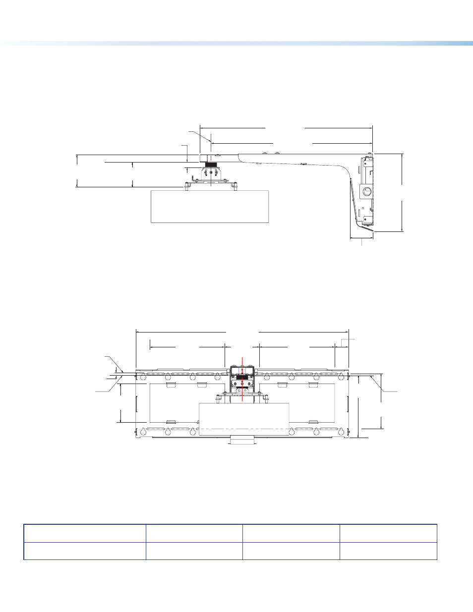
Aligning the Projector
When aligning the projector to the screen or wall display, consult the projector manual for the relevant throw
lengths. See the images below for the dimensions of USFM 100 with the UPB 25 installed.
Page 6 shows the USFM 100 specifications and page 7 shows the basic unit dimensions
.
www.extron.com