Usfm 100 installation guide, cont'd – Extron Electronics USFM 100 Installation imp User Manual
Page 4
4
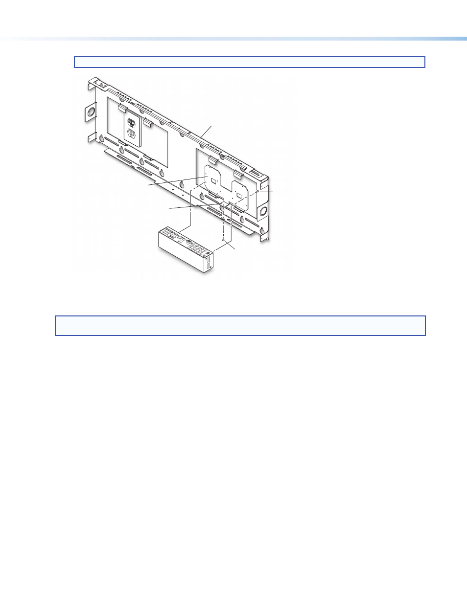
NOTE: Mount the switcher with the rear panel uppermost for ease of cable connection (see figure 4).
(1) 6-32 x 1/4" Screw
(2) 4-40 x 1/4" Screws
Mounting Plate
PoleVault
™
Switcher
Securing Tab
USFM 100 Base Plate
L
R
L
R
L
R
AU
X A
UDI
O
INP
UT
5
LINE
OU
T
VO
ICE
LIF
T
RECEIVE
R
PAG
ING
SEN
SOR
DO
NOT
GROUND
OR
SHO
RT
SPE
AKE
R
OUT
PUT
S
1B
R
GB
1A
RG
B
2B
RG
B
2A
R
GB
3B RG
B
/VIDEO
4B RG
B
/VIDE
O
3A R
GB
4A R
GB
I
N
P
U
T
S
RS-2
32
ML
C/I
R
2/4
/8
Ohms
CL
AS
S 2
W
IRI
NG
AM
PL
IFIE
D A
UD
IO
O
UT
VO
L/MU
TE
Tx
Rx
IR
12V
10V
50m
A
PO
WE
R
US
LIST
ED
17T
T
AU
DIO
/VI
DE
O
AP
PAR
ATU
S
®
RG
B
VID
EO
OUTP
UT
S
CO
NT
RO
L
N15
779
12V
5A
M
AX
Figure 4.
Attach Switcher to Mounting Plate and Secure to Base Plate
3. Run Cables
NOTE: All cable installation should be performed in accordance with local and national building codes, fire and
safety codes, and local and national electrical codes.
Run signal cables from the PoleVault input wallplates, control device location, and the speakers to the USFM 100
location. Cables can be routed behind the walls, through a surface raceway (such as Wiremold 700 or 2400), or
through conduit directly to the USFM 100.
USFM 100 Installation Guide, cont'd