Installation and operation, cont’d, Scp 250 • installation and operation, Wiring for use with a system 5cr plus switcher – Extron Electronics SCP 250 User Guide User Manual
Page 14
SCP 250 • Installation and Operation
Installation and Operation, cont’d
2-6
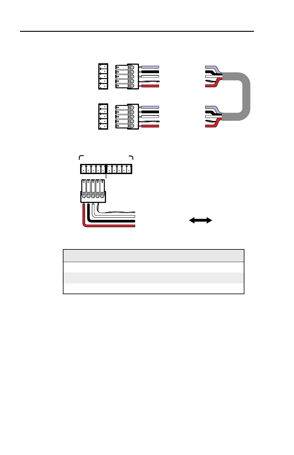
Wire both ends of the cable identically (pin A to pin A,
pin B to pin B, etc.).
IR signals in (violet)
Gnd (black)
Gnd (drain)
+12V (red)
Comm signal (white)
IR signals in (violet)
Gnd (black)
Gnd (drain)
+12V (red)
Comm signal (white)
System 5
AUX port
AUX
A
B
C
D
E
A
B
C
D
E
Port on
SCP
circuit
board
Wiring for use with a System 5cr Plus switcher
E
D
C
B
A
Ground (shield/drain)
Ground (black)
Comm. signal (white)
+12VDC (red)
1
2
SCP/AAP CONTROL
E D C B A
To / from
SCP 250
E D C B A
Wiring for use with a System 7SC switcher
Conductor gauges in Extron Comm-Link cables
red and black single strands
18 AWG
white and violet shielded single strands
22 AWG
drain wire
24 AWG
Connectors are included with each SCP, but the cable
must be purchased separately. See
for cable
part numbers. The cable should not exceed 300 feet
(91.4 meters) in length.
3
.
Plug one end of the cable into one of the SCP’s
communications connectors, and plug the other end into
the switcher (System 5cr Plus or System 7SC).
4
.
Cut a cable and attach connectors to it for each additional
SCP that will be connected in a daisy chain. Up to a total
of 16 SCPs
can be daisy chained together and connected to
the system switcher.
5
.
Plug one end of the cable into the SCP’s other
communications connector, and plug the other end into
a communications connector on the next SCP closer to