Extron Electronics RGB 202xi User Guide Rev. E User Manual
Page 16
Extron • RGB 202xi Series • User’s Manual
Rear Panel Connections
Page 2-3
_ This section describes function of each connector. Rear
Panel DIP switches are covered in Chapter 3.
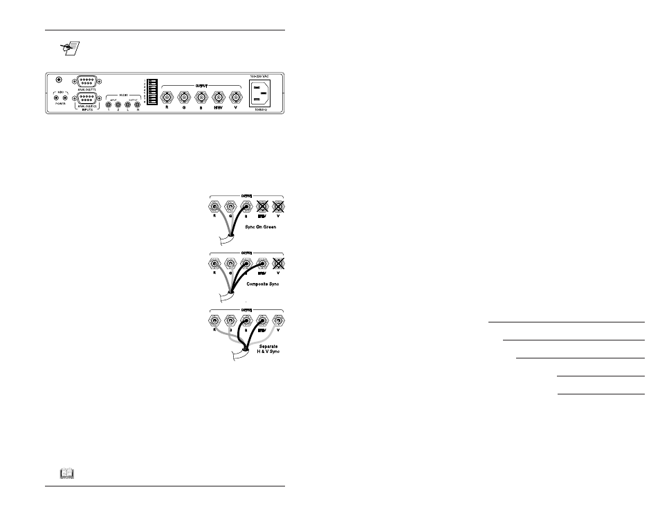
BNC Outputs with Auto Sync
The RGB 202
xi converts all computer video to RGB
Analog signals, with outputs on the rear panel BNC
connectors. With all of the DIP switches in the OFF
position, the RGB 202
xi is in the “Auto Sync” mode. This
means that it uses the BNC outputs that have an
impedance, by way of the attached cables. For example:
• If BNC connectors R, G and B
have cables attached (with 75ý
impedance) and H/V and V have
none, Auto Sync will use Sync
On Green as output.
• If BNC connectors R, G, B and
H/V have cables attached (with
impedance of 75ý for RGB and
less than 1ký for H/V), and V has
none, Auto Sync will use
Composite Sync as output.
• If BNC connectors R, G, B, H/V
and V have cables attached (with
75ý impedance for RGB and less
than 1ký for H/V and V), Auto
Sync will use Separate Horizontal
and Vertical Sync as output.
Sync Options
The Auto Sync feature can be altered by DIP switches
#1, #2 or #3 for specific sync processing.
Separate Horizontal and Vertical Sync - Separate
horizontal and vertical sync can be generated by setting
DIP switch #3 to the ON position. (See page 3-5.) When
using separate horizontal and vertical sync, the sync
polarity tracks the incoming polarity changes, unless
jumper 26 is set to force negative sync.
__ See Appendix B for special setup.
1
2
REMOTE
Extron • RGB 202xi Series • User’s Manual
A
Appendix A
Related Parts and Accessories
Computer-to-Interface Connections
MBC (Monitor Breakout Cables)
High Resolution BNC Cables
Partial List of MBCs
Remote Switch Box
RGB 202xi, RGB 202 VTG,
RGB 202 VS2 and RGB 202 VS SL2
User’s Manual