Mounting instructions, Under-desk mounting, Mounting instructions -4 – Extron Electronics MMX 42_62 Series User Guide User Manual
Page 9: Under-desk mounting -5, Installation, cont’d
MMX 42/62 Series Matrix Switchers • Installation
Installation, cont’d
2-4
MMX 42/62 Series Matrix Switchers • Installation
2-5
5
.
Reliable earthing (grounding)
— Maintain reliable
grounding of rack-mounted equipment. Pay particular
attention to supply connections other than direct
connections to the branch circuit (e.g. use of power strips).
Mounting instructions
On the 6-inch and 9.5-inch deep rack shelves, the switcher can
be mounted in the front or the rear of the rack.
1
.
Remove the feet from the bottom of the switcher, if they
are installed.
2
.
Mount the switcher using two 4-40 x 3/16 inch screws in
opposite (diagonal) corners to secure the unit to the shelf
(figure 2-2).
Use 2 mounting holes on
opposite corners.
(2) 4-40 x 3/16"
Screws
NOTE:
Using screws longer
than 3/16" will damage the
unit and void the warranty.
RSU 129 1U Universal Rack Shelf
Front false
faceplate
uses 2
screws.
1/2 Rack Width Front False
Faceplate
Figure 2-2 — Mounting the switcher on a standard
(9.5-inch) rack shelf
3
.
Install false faceplate(s) or other unit(s) to the rack shelf.
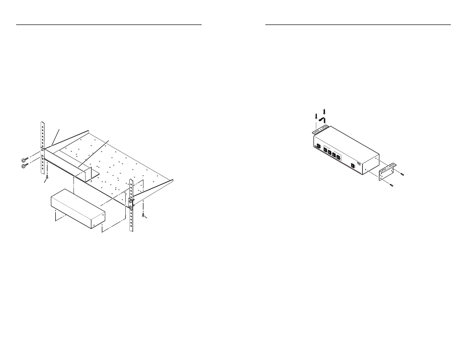
Under-desk mounting
Mount the unit to a desk or podium using the optional MBU 123
under desk mounting kit (part #70-212-01) as follows:
1
.
If rubber feet were previously installed on the bottom of
the unit, remove them.
2
.
Attach the mounting brackets to the switcher with the
machine screws provided (figure 2-3).
3
.
Hold the unit with the brackets attached against the
underside of the table or other furniture. Mark the location
of the screw holes of the bracket on the mounting surface.
CONFIG
AUDIO
VID
EO
OUTPUTS
1
2
4
2
3
1
INPUTS
MMX SERIES
Figure 2-3 — Under-desk mounting the MMX
4
.
Drill 3/32-inch (2 mm) diameter pilot holes, 1/4 inch
(6.3 mm) deep in the mounting surface at the marked
screw locations.
5
.
Insert #8 wood screws into the four pilot holes. Tighten
each screw into the mounting surface until just less than
1/4 inch (6.3 mm) of the screw head protrudes.
6
.
Align the mounting screws with the slots in the brackets
and place the unit against the surface, with the screws
through the bracket slots.
7
.
Slide the unit slightly forward or back, then tighten all four
screws to secure the unit in place.