Rear panel cabling, Power connection, Power connection -7 – Extron Electronics MMX 42_62 Series User Guide User Manual
Page 10: Installation, cont’d, Mmx 42/62 series matrix switchers • installation, Figure 2-8 — power connector wiring, Figure 2-8 shows how to wire the connector
MMX 42/62 Series Matrix Switchers • Installation
Installation, cont’d
2-6
MMX 42/62 Series Matrix Switchers • Installation
2-7
Rear Panel Cabling
All connectors are on the rear panel. The type and layout of the
connectors on the rear panel will vary, depending on the model
of the switcher. The rear panels of the MMX 42 series switchers
are similar to the MMX 62 series switcher, except they have four
rather than six video and audio input connectors.
5
6
2
1
2
4
3
1
0.5A MAX
12V
POWER
+
-
OUTPUTS
TX RX
RS-232
MMX 62 AV
INPUTS
INPUTS
OUTPUTS
1
L
R
2
L
R
3
L
R
1
L
R
4
5
6
2
L
R
L
R
L
R
L
R
1
2
4
6
8
10
Figure 2-4 — MMX 62 AV rear panel
TX RX
RS-232
2
1
0.5A MAX
12V
POWER
+
-
OUTPUTS
MMX 42 SV A
OUTPUTS
1
L
R
2
L
R
INPUTS
1
L
R
2
L
R
4
5
L
R
L
R
2
4
3
1
INPUTS
1
3
5
6
8
10
Figure 2-5 — MMX 42 SVA rear panel
5
6
2
1
2
4
3
1
0.5A MAX
12V
POWER
+
-
OUTPUTS
R
L
2
1
6
5
3
4
1
2
INPUTS
INPUTS
OUTPUTS
MMA 62 AV RCA
TX RX
RS-232
1
2
4
7
9
10
Figure 2-6 — MMX 62 AV RCA rear panel
2
1
0.5A MAX
12V
POWER
+
-
OUTPUTS
R
L
R
L
2
1
3
4
1
2
INPUTS
OUTPUTS
MMX 42 SVA RCA
TX RX
RS-232
2
4
3
1
INPUTS
1
3
5
7
9
10
Figure 2-7 — MMX 42 SVA RCA rear panel
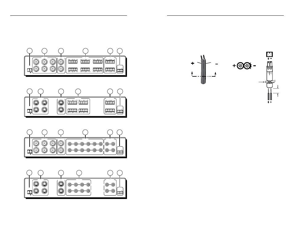
Power connection
a
Power connector — Plug the external 12 V power supply
into this 2-pole captive screw connector. The power supply
is included with the unit. No damage will result if the power
connector is wired incorrectly, but the unit will not power up.
Figure 2-8 shows how to wire the connector.
Power Supply
Output
Cord
Captive Screw Connector
SECTION A–A
Ridges
Smooth
A
A
Tie Wrap
3/16”
(5 mm) Max.
Figure 2-8 — Power connector wiring
C
The length of the exposed (stripped) copper wires is
important. The ideal length is 3/16 inch (5 mm).
Longer bare wires can short together. Shorter wires
are not as secure in the direct insertion connectors and
could be pulled out.
Use the supplied tie-wrap to strap the power cord to the
extended tail of the connector.
N
Do not tin the power supply leads before installing in the
direct insertion connector. Tinned wires are not as secure
in the connectors and could be pulled out of the connector.