Mgp pro and windowall, Pro series • setup guide (continued), Three composite video – Extron Electronics MGP Pro and WindoWall Pro Series Setup Guide User Manual
Page 2: On the rear panel diagram on page 1)
3.
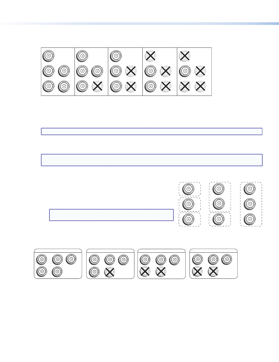
Connect input sources to the BNC, HDMI, and 3G/HD-SDI input connectors. The inputs can accept the following signals:
z
RGB, HD/SD component, S-video, and composite video inputs 1, 2, 3, and 4 — RGB, component video,
S-video, or composite video (fully configurable)
RGBHV
Video
RGsB or
Component
Video
S-Video
Composite
Video
RGBS or
RGBcvS
Video
H
/HV
V
R
/R-Y
G
/Y
VID
B
/C
B-Y
H/HV
B/C
B-Y
H
/HV
V
R
/R-Y
G
/Y
VID
B
/C
B-Y
V
R/R-Y
G/Y
VID
B
/C
B-Y
H/HV
V
R/R-Y
G/
Y
VID
B
/C
B-Y
H/HV
V
R/R-Y
G/Y
VID
1
1
1
1
1
z
HDMI inputs 1, 2, 3, and 4 (DI and SDI models only) — Any of these inputs can be used instead of or in combination
with analog inputs 1 through 4. However, the MGP Pro cannot process input from two different source devices
connected to HDMI or 3G-SDI and BNC connectors with the same input number (for example, input 1) at the same time.
z
3G-SDI inputs 1 and 2 (SDI models only) — Either of these inputs can be used instead of or in combination with
analog input 1 or 2.
NOTE: Standard definition SDI is not supported on these 3G/HD-SDI inputs.
z
Live Background input — HDMI for live background video only (available on all models). The two or four MGP Pro
windows are displayed in front of this background image. When a live background is used, the MGP Pro output is locked
to the input rate of the live background. This input is not scaled.
NOTE: This input connector can be used only to receive the background image. The input is not scaled or
processed. To process HDMI input signals, you must use a DI or SDI model.
z
Virtual inputs (not supported on WindoWall Pro models) — Component
video, S-video, or composite video. These virtual inputs can be
configured only via the Windows-based control software or SIS (Simple
Instruction Set) commands. In each column of connectors, you can
connect inputs as follows:
z
Three composite video
z
One S-video and one composite video
NOTE: The S-video input must be connected to the top two
BNC connectors in the column (Y on top, C second).
z
One interlaced component video (connects to all three BNC
connectors in the column)
4.
Attach an output device to the analog BNC connectors (shown below) or to the HDMI output connector.
R
/R-Y
G
/Y
B
/B-Y
H
/HV
V
RGBHV
R
/R-Y
G
/Y
B
/B-Y
H
/HV
V
RGBS
R
/R-Y
G
/Y
B
/B-Y
H
/HV
V
RGsB
R
/R-Y
G
/Y
B
/B-Y
H
/HV
V
HD YUV Component Video
5.
If the MGP Pro will be connected to a computer or to a host controller for remote control, connect an RS-232 cable from the
host to the 9-pin D RS-232/422 rear panel connector or the front panel 2.5 mm TRS Config port. The default protocol for both
ports is 9600 baud, 1 stop bit, no parity, 8 data bits, and no flow control.
Alternatively, you can connect an RJ-45 network cable to the rear panel LAN port for remote control.
6.
Connect power to the MGP Pro by plugging a standard IEC power cord (provided) from a 100 to 240 VAC, 50-60 Hz power
source into the power receptacle (
l
on the
on page 1).
7.
Connect power to all other devices and power them on.
VID
Y
VID
B-Y
C
VID
R-Y
5
6
7
VID
Y
VID
B-Y
C
VID
R-Y
5
6
7
S-video and
Composite
Component
VID
Y
VID
B-Y
C
VID
R-Y
5
6
7
Composite
MGP Pro and WindoWall
®
Pro Series
• Setup Guide (Continued)
2