Extron Electronics MGP Pro and WindoWall Pro Series Setup Guide User Manual
Mgp pro and windowall, Pro series • setup guide, Rear panel features and connections
MGP Pro and WindoWall
®
Pro Series • Setup Guide
The MGP Pro and WindoWall Pro Series are multi-window video signal processors that can display multiple video sources
on a single screen in picture-in-picture or picture-by-picture format. The processors can switch among inputs and presets.
The available models are listed below. The MGP 464 Pro and WindoWall Pro models display up to four windows while the
MGP 462 Pro models display one or two.
The WindoWall Pro Series products are designed for videowall systems and are available in sets of two or three processors.
These models have no front panel controls and are controllable only via software.
The following input configurations are available:
z
Standard MGP 464 Pro, MGP 462 Pro, and WindoWall Pro — Four sets of BNC inputs that accept RGB, component
video, S-video, and composite video signals
z
MGP 464 Pro DI, MGP 462 Pro DI, and WindoWall Pro DI — Four sets of BNC inputs and four HDMI inputs
z
MGP 464 Pro 3G-SDI and MGP 462 Pro 3G-SDI — Four sets of BNC inputs, two 3G/HD-SDI inputs, and two HDMI
inputs
All MGP Pro models have 15 virtual inputs on BNC connectors.
This guide provides procedures for installing all MGP 464 Pro and MGP 462 Pro models, and for configuring all models except the
WindoWall Pro series. To configure the WindoWall Pro models (done only using software), see the WindoWall Console help file or
the WindoWall Console Quick Reference card.
NOTE: For full installation, configuration, and operation details, see the MGP Pro Series User Guide or the WindoWall Pro
Series User Guide
.
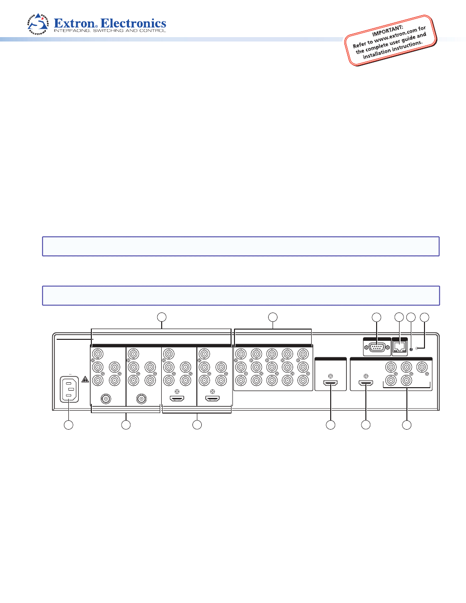
Rear Panel Features and Connections
NOTE: The illustration below shows an MGP 464 Pro 3G-SDI. The rear panels of the other MGP Pro and WindoWall Pro
models are the same except for the number and types of input connectors.
HDMI
3G/HD-SDI
3G/HD-SDI
HDMI
-A MAX
100- 240V
50/60 Hz
MGP/WINDOWALL PRO SERIES
1
R
R-Y
G/Y
VID
B/C
B-Y
H/HV
V
2
R
R-Y
G/Y
VID
B/C
B-Y
H/HV
V
RESET
5
6
7
VID
Y
VID
B-Y
C
VID
R-Y
8
9
10
VID
Y
VID
B-Y
C
VID
R-Y
11
12
13
VID
Y
VID
B-Y
C
VID
R-Y
14
15
16
VID
Y
VID
B-Y
C
VID
R-Y
17
18
19
VID
Y
R/
R-Y
H/
HV
G/Y
B/
B-Y
V
RS-232/422
VID
B-Y
C
VID
R-Y
3
R
R-Y
G/Y
VID
B/C
B-Y
H/HV
V
4
R
R-Y
G/Y
VID
B/C
B-Y
H/HV
V
INPUTS
HDMI
HDMI
OUTPUTS
VIRTUAL INPUTS
BACKGROUND
LAN
REMOTE
2
7
10
1
5
3
4
6
8
11
12
9
a
BNC inputs 1 through 4
b
Virtual inputs 5 through 19
c
Remote RS-232/422 connector
d
LAN connector
e
Reset button
f
Reset LED
g
BNC output connectors
h
HDMI output connector
i
HDMI live background input
j
HDMI inputs (DI and SDI models only)
k
3G/HD-SDI inputs (3G-SDI models only)
l
AC power connector
Installation Steps
1.
Install the four rubber feet on the bottom of the MGP Pro, or mount the unit using the supplied rack mounting brackets (see
the instructions provided with the mounting kit).
2.
Turn off power to the input and output devices, and remove the power cords from them.
Product Category
1