Mounting, Panels and locations of features, Front panel features – Extron Electronics IPL Pro Series Setup Guide User Manual
Page 3: Rear panel features, Rear panel, Features, Ipl pro series front panel features, Ipl pro series rear panel features, Com (serial) leds com (serial) leds reset button, Reset button
3
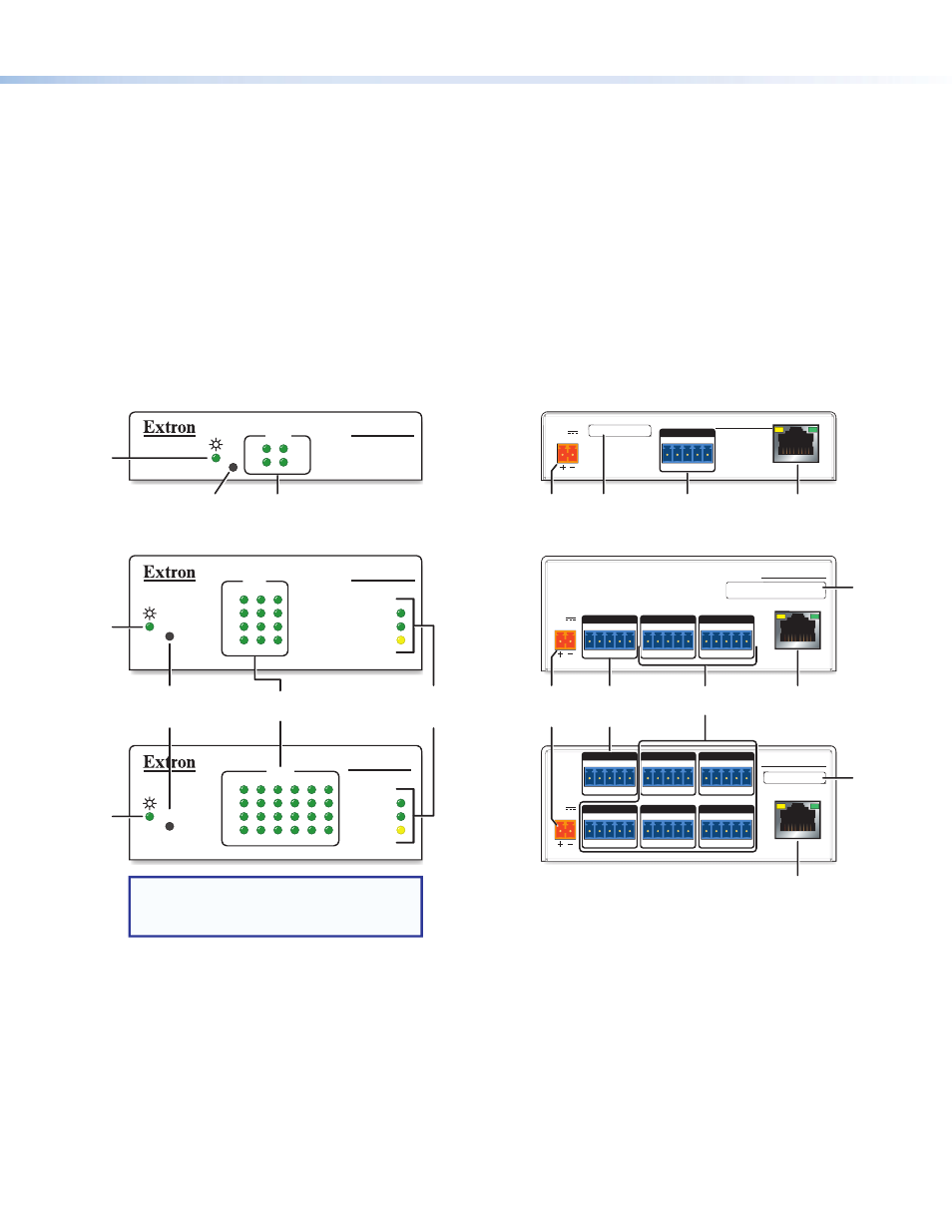
Front Panel Features
R
1000
LINK
ACT
COM
3
1
2
6
4
5
RTS
CTS
Tx
Rx
R
1000
LINK
ACT
IPL PRO S3
3
1
2
RTS
CTS
Tx
Rx
COM
COM
RTS
CTS
Tx
Rx
R
IPL PRO S1
IPL PRO S6
NOTE: Numbers adjacent to LEDs
correspond to the like-numbered
rear panel ports.
COM (Serial)
LEDs
COM (Serial)
LEDs
Reset
Button
(recessed)
Reset
Button
(recessed)
Power
LED
Power
LED
Power
LED
LAN/
Network
LEDs
Figure 2.
IPL Pro Series Front Panel Features
Rear Panel Features
POWER
12V
0.2A MAX
POWER
12V
X.XA MAX
POWER
12V
X.XA MAX
IPL PRO S3
LAN / PoE
G
Tx Rx
RTS CTS
COM
G
Tx Rx
RTS CTS
COM 1
G
Tx Rx
RTS CTS
COM 3
G
Tx Rx
RTS CTS
COM 2
G
Tx Rx
RTS CTS
COM 1
G
Tx Rx
RTS CTS
COM 3
G
Tx Rx
RTS CTS
COM 2
G
Tx Rx
RTS CTS
COM 4
G
Tx Rx
RTS CTS
COM 6
G
Tx Rx
RTS CTS
COM 5
LAN / PoE
IPL PRO S6
IPL PRO S1
LAN / PoE
MAC: 00-05-A6-XX-XX-XX
S/N: ####### E######
MAC: 00-05-A6-XX-XX-XX
S/N: ####### E######
MAC: 00-05-A6-XX-XX-XX
S/N: ####### E######
MAC: 00-05-A6-XX-XX-XX
S/N: ####### E######
00-05-A6-XX-XX-XX
5-pole COM
RS-232 ports
5-pole COM
RS-232/RS-422/
RS-485 ports
MAC
address
Power
input
connector
Power
input
connector
MAC
address
MAC
address
LAN/PoE (Ethernet)
connector and LEDs
5-pole COM
RS-232 port
LAN/PoE
(Ethernet)
connector and LEDs
LAN/PoE (Ethernet)
connector and LEDs
Figure 3.
IPL Pro Series Rear Panel Features
Panels and Locations of Features
Location and quantity of LEDs and corresponding connectors vary by model, but the functions and port wiring are identical
across models for each port type.
Mounting
Securely mount the control processor and other devices and attach cables using the wiring section (
page 4) as a wiring guide. Optional 1U rack shelves and furniture mounting bracket kits are available for use with the control
processor. Read the instructions and UL guidelines that come with the rack shelf or mounting kit for installation procedures.
See the product-specific page at
ol processor.