Dipswitch settings – Extron Electronics IN2013HR User Manual
Page 9
7
©2000 - INLINE, Inc.
IN2013HR Operation Manual - V1.0 12/05/00
Horizontal Position Control Enable / Disable
The factory default setting is horizontal position control enabled. In rare cases (depending on the
design of the display device sync circuitry), you may have to disable the horizontal position
control to achieve a solid image on the display device. The horizontal position control may be
enabled or disabled by setting the dipswitch 1 in SWITCH Bank 1 as indicated in the chart at the
bottom of the page.
Dipswitch Settings
Two dipswitch panels are easily accessed through windows on the bottom of the IN2013HR. The
SWITCH 1 panel regulates the output sync format (dipswitches 1-7) and controls the input signal
configuration (dipswitches 8-10). The SWITCH 2 panel determines the monitor emulation settings.
SWITCH 1
For most installations, the IN2013HR will be operated in the factory default mode and will not
require any changes to the dipswitch settings. The factory default settings are:
SWITCH 1 Dipswitches ON:
1, 3, 5, 6, 7 & 8
Output Signal Format:
Auto Sense Enabled - Interface Selects Format
Horizontal Position Control:
Enabled
H & V Sync Polarity:
Mirror
Input
Polarities
Monitor Emulation (SWITCH 2):
Disabled (all Dipswitches on SWITCH 2 panel are set to 0)
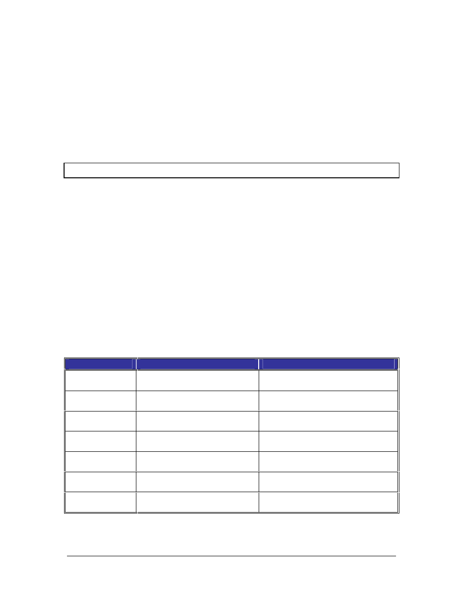
The following table lists the functions of the first 7 dipswitches in SWITCH 1:
Dipswitch
Function
Setting
1
Horizontal Position Control
1 = Enabled*
0 = Disabled
2
Output Sync Format:
Sync on Green
1 = Sync on Green
0 = RGBHV / RGBS*
3
Output Sync Format
RGBHV / RGBS
1 = RGBHV*
0 = RGBS
4
Output Sync Polarity
1 = Forced Negative
0 = Mirror Input*
5
Output Sync Format:
Auto Sense / Manual
1 = Auto Sense*
0 = Manual
6
Serration Pulses
1 = Serrations Present*
0 = No Serrations
7
Output Video Format:
Green / Monochrome Video
1 = Green*
0 = Monochrome on Green BNC
*Factory Default Settings