Installation – Extron Electronics IN2013HR User Manual
Page 5
3
©2000 - INLINE, Inc.
IN2013HR Operation Manual - V1.0 12/05/00
Installation
This section offers step-by-step instructions for installing the IN2013HR Computer Video
Interface. An Application Diagram is included on page 5.
1. Turn the Computer and Computer Monitor Off - Disconnect the computer monitor from
the computer’s video port.
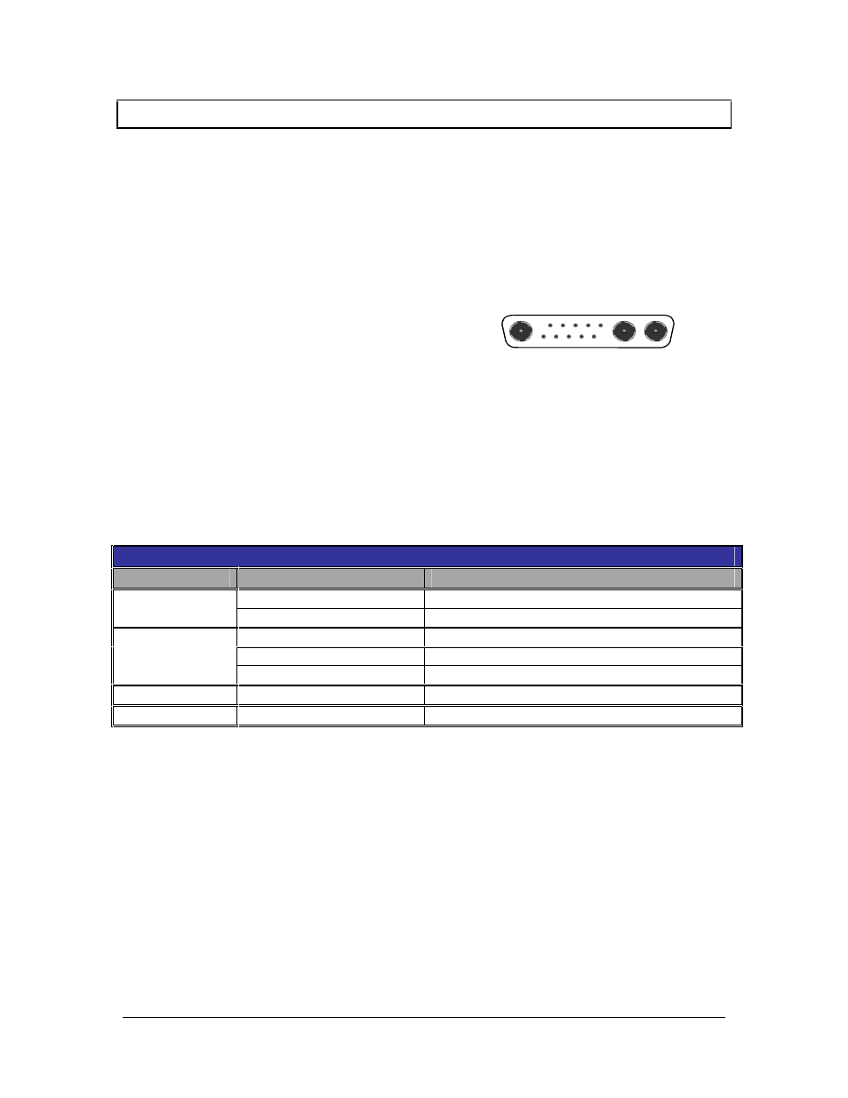
2. Connect the Permanently Attached IN2013HR Input Cable - to the computer’s video output
port (see illustration on the right). For cable
runs that are longer than 3’, the IN8400
Series 13W3 Workstation Extension Cables
are available in lengths ranging from 6’ to
50’.
3. Check the Input Signal Configuration Settings - (SWITCH 1 - Dipswitches 8 / 9 / 10)
which are on the bottom of the IN2013HR. The factory default settings for dipswitches 8, 9
and 10 will work with Sun workstations and most SGI computers. For other computers,
carefully set dipswitches 8, 9 and 10 as indicated in the chart below:
Note: These settings only relate to the input signal from the computer and have no effect on the
output sync format.
Computer Input Selection Dipswitch Chart
Workstation
Input Signal
8/9/10
Dipswitch Setting - Switch Bank 1
RGBS (most common)
000 - Composite Sync on pin 5
SUN
RGBHV
101 - Hor. sync on pin 6; Vert. sync on pin 2
RsGsBs (most common)
001 - Sync on green
RGBS
011 - Composite Sync on pin 3
SGI
RGBHV
100 - Hor. sync on pin 4; Vert. sync on pin 5
NeXT Color
RGsB
001 - Sync on green
IBM PowerPC
RGBHV
010 - Hor. sync on pin 5; Vert. sync on pin 9
4. Connect the IN2013HR Video Output - (5 BNC connectors) to the data display device's
RGB input, using three, four, or five high-resolution BNC cables or a multi-conductor
RGBHV, RGBS, or RGB "snake". The IN7000 Series, IN7200 Series, IN7300 Series and
IN7400P Series high-resolution cables are well suited for this purpose. Take care while
making connections to insure that the red output is connected to the red input, green output to
the green input, etc.
5. Select the Output Sync Format - The interface normally selects an output format
automatically according to the number of cables connected to the output. If you wish to
override the automatic output format feature and manually select a specific format, set the
dipswitches as necessary according to the chart on page 8 (see Output Sync Format -
Manual Mode).