Installation and operation, cont’d, Vcr control rew play fwd pause stop tx, Signal ir link – Extron Electronics IR Link User Manual
Page 9
IR Link • Installation and Operation
IR Link • Installation and Operation
Installation and Operation, cont’d
2-8
To 1–2 additional
IR Control Modules
(IRCMs)
IR Link Infrared Repeater
rear view
IR Emitter
(Connect 1 per
each IRCM.)
IRCM #1
rear view
MLC 206 rear view
IRCM #2
rear view
To an
MLS
switcher
RS-232
projector
connection
MLM faceplate
A
D
B C
E
A
D
B C
E
ON
1
2
MLC
IR / RCM
port
A B C D
IR / RCM
Control
Module
Control Module
IR Link
D
C
C
Modulated IR (IR Link)
+12VDC
Control signal (IRCM)
Ground ( )
D
B
B
A
D
B
A
A
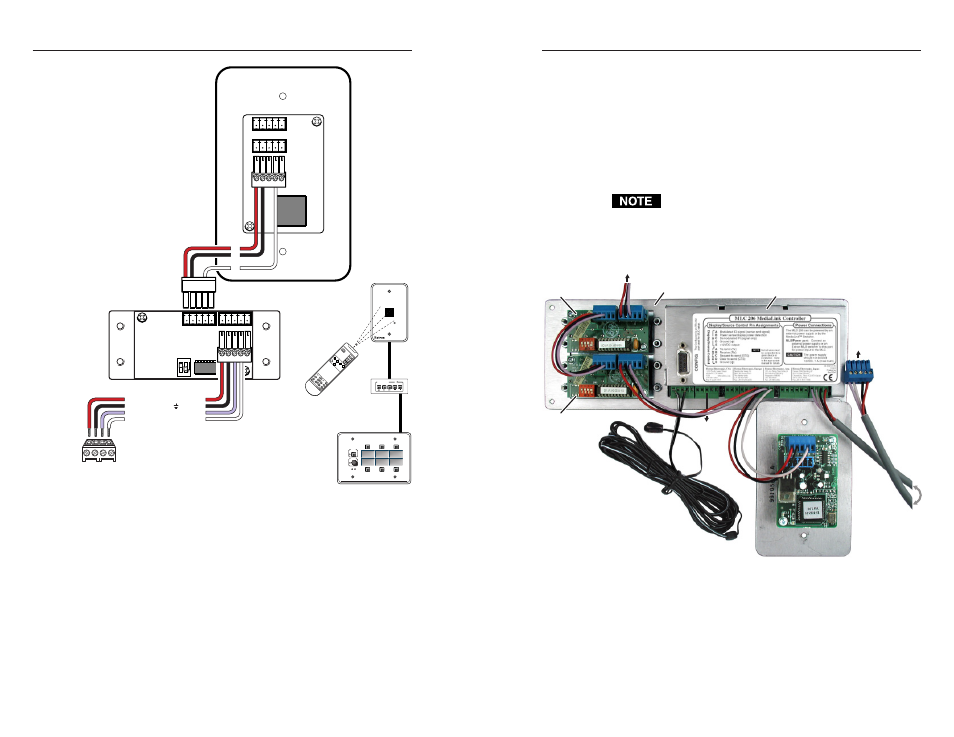
MLC 206 to a Control Module to an IR Link
VCR CONTROL
REW
PLAY
FWD
PAUSE
STOP
Tx
MLC 206
Extron
MediaLink Controller
MLC 206
DISPLAY
POWER
VOLUME
MAX/
MIN
VCR
DVD
Laptop
IR Link
MLA
Remote
SIGNAL
IR LINK
Total
distance
from MLC:
150' (45.7 m)
max.
Connectors are included with the IR Link, but the cable
must be purchased separately. See appendix A for cable
part numbers.
3.
Plug the 5-pole connector into one of the IR Link’s
communications connectors.
4.
Cut a length of cable and attach 5-pole connectors to both
ends of it for each additional MediaLink control module
that will be connected in a daisy chain. Wire both ends of
the cable identically (pin A to pin A, pin B to pin B, etc.).
Up to a total of 4 control modules in any combination of
models and one IR Link can be daisy chained together and
connected to the MLC as long as each control module has a
2-9
unique address Refer to the Control Modules User’s Manual
and the Relay Control Modules User’s Manual for details on
addresses and DIP switches.
5.
Plug one end of the cable into the IR Link’s remaining
communications connector, and plug the other end into a
communications connector on the control module. The
photo below shows an IR Link and control modules (IRCMs,
ACMs, RCMs, and/or CMs) connected to an MLC in a
typical daisy chain setup.
Do not connect more than one IR Link (either in parallel
or in series) to an MLC. Also, do not connect more than
four control modules to an MLC.
An IR Link and control modules connected to an MLC
6.
Connect one Extron IR Emitter to the MLC’s Display/
Source Control IR connector for each control module that
is part of the system, or connect an Extron IR Broadcaster
instead.