Preparing the table, Cabling and installing the aaps, Dressing the cables – Extron Electronics Hideaway Surface Access Products User Manual
Page 2: Internal rj-45 cable routing, Warning, Cautions, Caution
2
Preparing the Table
WARNING:
Wear safety glasses when cutting the hole in the table. Failure to comply may result in eye injury.
CAUTIONS
:
•
The opening in the table for the HSA should be cut only by licensed and bonded craftspeople.
•
Exercise care to prevent scarring or damaging the furniture.
•
Ensure that the table surface is:
•
at least 3/8 inch (0.325") (9.5 mm) thick and
•
no more than 1-3/4 inch (1.75") (44.5 mm) thick.
Cut a hole in the surface where the enclosure will be installed. There are three methods for cutting the hole in the table:
z
A hand router and the appropriate Extron HSA routing template.
HSA 200
USER A
CCESS
HSA 200
CABLE CUBBY 300
CABLE CUBBY 300
USER A
CCESS
See the table below for part numbers. See the HSA Series and HSA Routing
Template User Guide, available on the Extron website,
www.extron.com
, to
prepare the template and use the template to cut the hole.
NOTE: The metal routing template is reusable. Do not discard this
routing template when the installation is complete.
z
A CNC wood router and the exact cut-out dimensions for your model. See the
table below for cut-out dimensions:
z
A jigsaw and a paper cut-out template (available on the Extron website,
www.extron.com
)
NOTE: The underlined dimension in the table below is the AAP and
connector access side.
Template
Part Number
Surface Cut-out Dimensions
Product
Width
Depth
HSA 400 (USA)
70-189-01
8.14 inches (20.68 cm)
5.95 inches (15.11 cm)
HSA 400 (Int’l)
70-189-02
9.64 inches (24.49 cm)
5.95 inches (15.11 cm)
HSA 402 (USA)
70-190-01
10.37 inches (26.34 cm) 5.95 inches (15.11 cm)
HSA 402 (Int’l)
70-190-02
13.37 inches (33.96 cm) 5.95 inches (15.11 cm)
HSA 822 (all regions)
70-191-01
8.03 inches (20.40 cm)
8.33 inches (21.16 cm)
Mounting the HSA in the Table and Connecting Cables
CAUTION:
Be careful when handling and mounting the enclosure.
Mishandling can damage the appearance of the enclosure.
1.
Unbolt the clamshell from the enclosure (its shipped position).
2.
Remove the plastic strips that protect the corners of the enclosure and the plastic
film on the finished surfaces.
3.
Carefully lower the HSA into the hole to test the fit. If necessary, carefully enlarge
the opening.
4.
Under the table, bolt the clamshell to the enclosure with two bolts of optimum
length.
5.
Under the table, connect the RJ-45 connectors.
z
The network cables are terminated in accordance with the TIA/EIA T 568 A
standard inside the HSA.
z
See the drawings on the next page to understand the relationship between the
RJ-45 connectors on the bottom of the unit to the connectors on the faces of
the unit.
3
User Access
Cut-Out
Template f
or Extron's
Cable Cubb
y 200
.350" (0.90 cm
)
Print this
template
at 100%
Trim Ring
Lip
Trim Ring’
s Outer Edge
0.00”
(0.00 cm)
0.02 (0.05 cm)
+
1. Confirm Pr
oduct to be installe
d
2. Measure cutout and template
3. Af
ter
ch
ecking,
cut opening
e
g
HSA 400
COMPUTER
125 - 50/60 Hz 5A
HSA 400
3
4
5
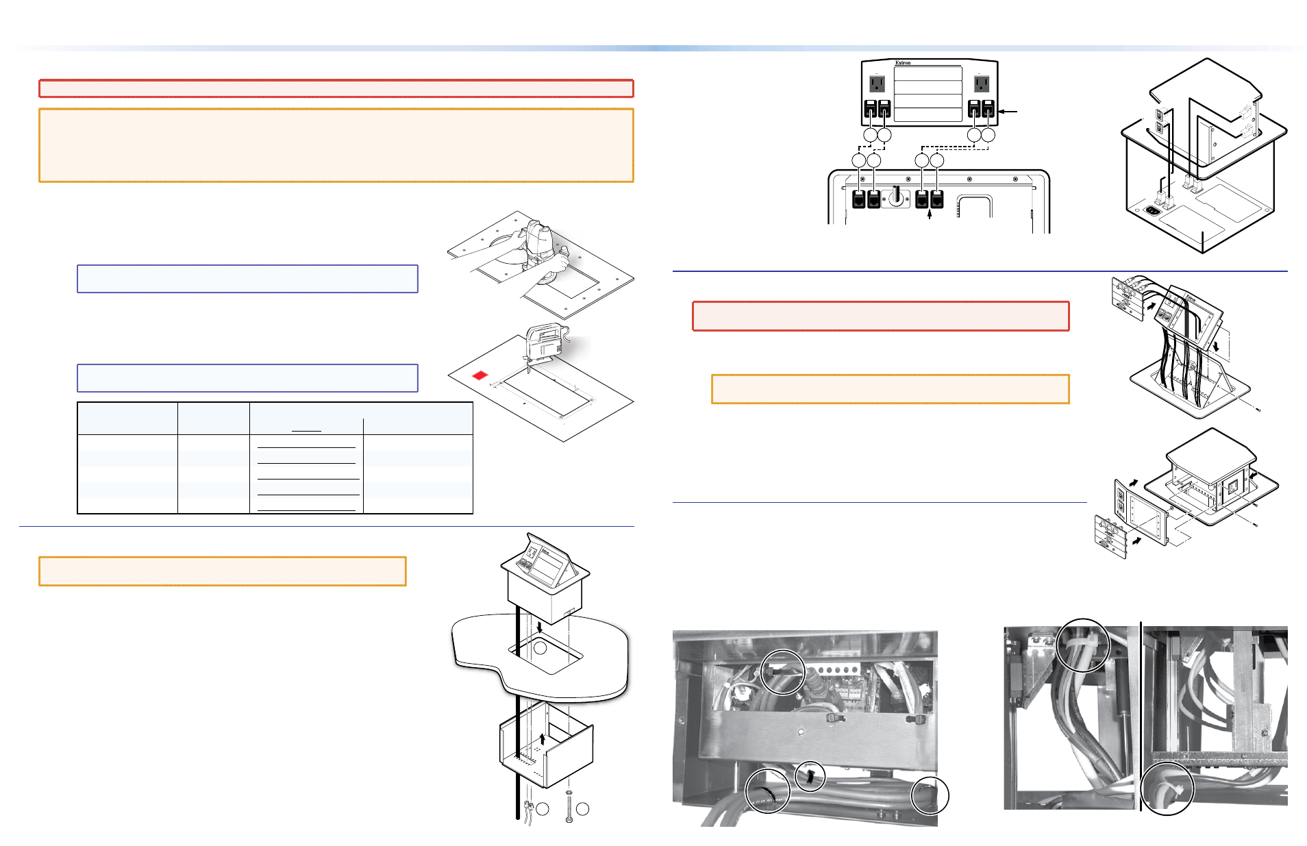
Internal RJ-45 Cable
Routing
Cabling and Installing the AAPs
WARNING:
Ensure that AC power is disconnected before removing the front
panel.
1.
Remove and retain the four screws on the right and left sides of the front panel.
Lift the panel away from the enclosure.
CAUTION:
On the HSA 822, do NOT remove the center screws. They do not
fasten the AAP panel in place. They secure the AC power outlet.
2.
Secure each AAP to the panel with the provided #4-40 nuts.
3.
Route the AAP cables through the hole in the underside of the HSA and connect
them to the rear of the AAPs.
4.
Reinstall the front panel in the enclosure and secure it in place with the screws
removed in step 1.
Dressing the Cables
1.
Lift the HSA to extend the AAP cables to their maximum pull.
2.
Experiment with AAP cable positioning to ensure that the cables do not rub
against any edges and that the cable pull does not restrict the HSA lifting
movement. The figures below show the recommended cable routing.
3.
Route the cables as recommended in the photos below. Secure
the cables in the circled locations with the provided zip ties.
HSA 400
(shown w/ cables)
HSA 400
125 - 50/60 Hz 5A
Do not
Remove
Center
Screw
HSA 822
HSA 822
HSA 402 Rear View
HSA 822
View from
one side
Shown with clamshell removed
for clarity.
View from the opposite side
HSA 402
120-240 50/60 Hz 5A
120-240 50/60 Hz 5A
A1
A2
B1
B2
A1
A2
B1
B2
A B
A B
C D
C D
HSA 822
HSA 400 / HSA 402
Present on
HSA 402 Only
Present on
HSA 402 Only
HSA 400 / 402 / 822 • Installation Guide