Operation, Rs-232 and ir connector wiring – Extron Electronics DTP HDMI 301 User Guide User Manual
Page 17
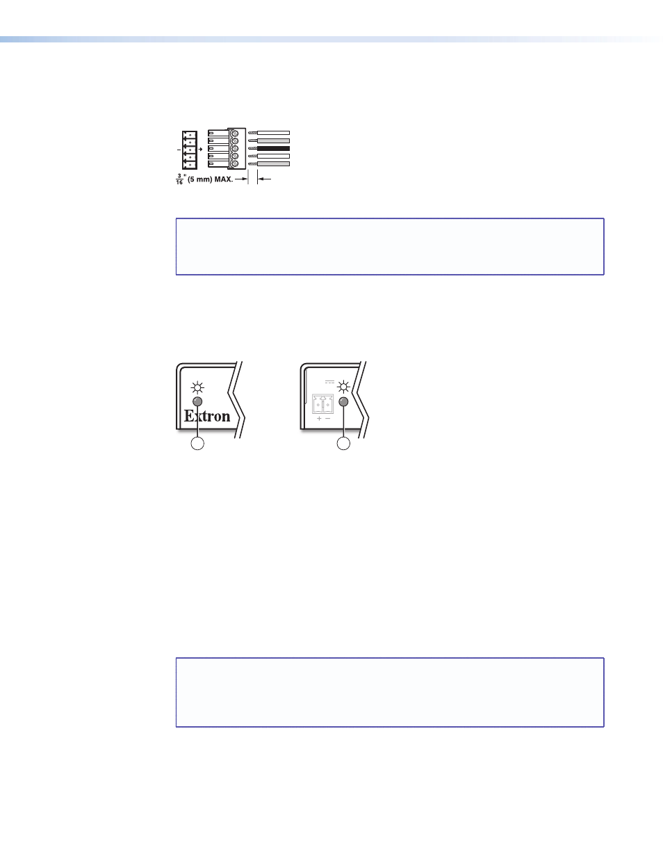
RS-232 and IR connector wiring
Figure 12 shows how to wire the RS-232 connector.
Ground
Receive pin on connected unit
Transmit pin on connected unit
Connected RS-232
and IR Device Pins
Tx/Rx
Pins
Receive pin on connected unit
Transmit pin on connected unit
Rx
Tx
RS-232
IR
Rx
Tx
Figure 12.
RS-232 Connector Wiring
NOTE: The length of exposed wires is important. The ideal length is 3/16 inch (5 mm).
See the
on page 6 for details.
Do not tin the power supply leads before installing them in the connector.
Tinned wires are not as secure in the connector and could be pulled out.
Operation
Figure 13 shows the location of the power indicators on the front and rear panels of the
transmitter and receiver.
Rear Panel
Rear Panel
Front Panel
Front Panel
POWER
12V
0.6 A MAX
2
1
Figure 13.
Power Indicators
a
Power (and signal) LED (front panel) —
Amber — The unit is receiving power, either locally or remotely (on the DTP cable).
Green — The unit is receiving an active HDMI signal, either on the HDMI input if a
transmitter, or transmitted on the DTP cable if a receiver.
b
Power LED (rear panel) —
Amber — The unit is receiving power remotely (on the DTP cable).
Green — The unit is receiving power locally.
After the transmitter, the receiver, and their connected devices are powered up, the system
is fully operational. If any problems are encountered, ensure all cables are routed and
connected properly.
NOTE: Ensure that the video source and display selected for the DDC are properly
connected to the transmitter and receiver pair, and that the transmitter, the
receiver, and the display have power applied before power is applied to the
video source. If the other devices are not turned on before the video source, the
image may not appear.
DTP HDMI 301 • Installation and Operation
11