Pin assignments and wiring, Hdmi connector, For pin assignments and to use the lockit – Extron Electronics DTP HDMI 301 User Guide User Manual
Page 13: For pin assignments and to use the lockit hdmi
Pin Assignments and Wiring
HDMI connector
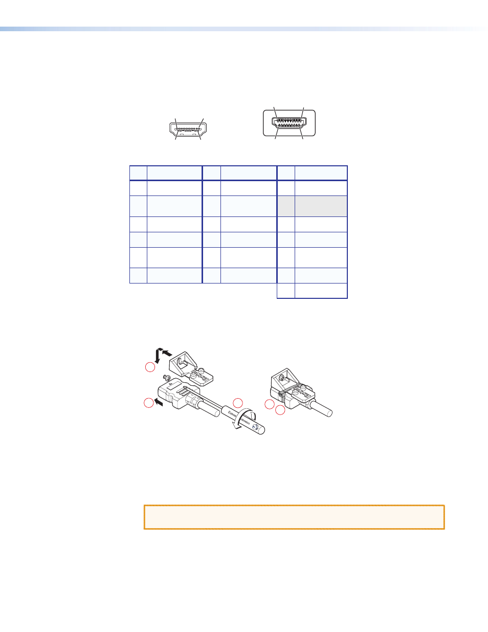
Figure 5 defines the pinout for the HDMI connector.
Pin
Signal
1
TMDS data 2+
TMDS data 2-
TMDS data 0–
TMDS clock-
+5 V power
Hot plug detect
CEC control
Reserved
(NC)
TMDS data 1+
TMDS clock+
TMDS clock
shield
SDA
DDC / CEC
Ground
TMDS data 2
shield
Pin
Pin
Signal
Signal
2
7
13
4
10
16
11
17
12
18
19
14
3
TMDS data 0-
TMDS data 0
shield
8
9
SCL
15
TMDS data 1-
TMDS data 1
shield
5
6
HDMI
HDMI
Type A Receptacle
Type A Plug
1
18
2
19
1
18
2
19
Figure 5.
HDMI Connector
To securely fasten an HDMI cable to a device:
1.
Plug the HDMI cable into the panel connection (see figure 6).
3
3
1
2
4
5
Figure 6.
Installing the LockIt Lacing Bracket
2.
Loosen the HDMI connection mounting screw from the panel enough to allow the
LockIt lacing bracket to be placed over it. The screw does not have to be removed.
3.
Place the LockIt lacing bracket on the screw and against the HDMI connector, then
tighten the screw to secure the bracket.
CAUTION: Do not overtighten the HDMI connector mounting screw. The shield it
fastens to is very thin and can easily be stripped.
4.
Loosely place the included tie wrap around the HDMI connector and the LockIt lacing
bracket as shown.
5.
While holding the connector securely against the lacing bracket, use pliers or similar
tools to tighten the tie wrap, then remove any excess length.
DTP HDMI 301 • Installation and Operation
7