Installation checklist, Routing and connecting cables, Planning (page 1) – Extron Electronics Cable Cubby 700 User Manual
Page 6: Preparing the table (page 2), Preparing the cable cubby (page 3), Mounting the cable cubby in the table (page 4)
68-2491-50
Rev. B
05 14
6
Extron Headquarters
+800.633.9876 Inside USA/Canada Only
Extron USA - West
Extron USA - East
+1.714.491.1500 +1.919.850.1000
+1.714.491.1517 FAX
+1.919.850.1001 FAX
Extron Europe
+800.3987.6673
Inside Europe Only
+31.33.453.4040
+31.33.453.4050 FAX
Extron Asia
+65.6383.4400
+65.6383.4664 FAX
Extron Japan
+81.3.3511.7655
+81.3.3511.7656 FAX
Extron China
+86.21.3760.1568
+86.21.3760.1566 FAX
Extron Middle East
+971.4.299.1800
+971.4.299.1880 FAX
Extron Korea
+82.2.3444.1571
+82.2.3444.1575 FAX
Extron India
1800.3070.3777
(Inside India Only)
+91.80.3055.3777
+91.80.3055.3737 FAX
©
2014 Extron Electronics All rights reserved. All trademarks mentioned are the property of their respective owners.
www.extron.com
Installation Checklist
Planning (page 1)
Check with local and state regulations before starting the installation.
Check all parts and equipment before installation.
Preparing the Table (page 2)
Determine the best location for the enclosure.
Choose a method for cutting the hole in the table.
Preparing the Cable Cubby (page 3)
Choose and assemble a combination of AAPs, cable-pass through, and retractor connectivity to populate
the Cable Cubby.
Secure the connectivity modules and power module in the Cable Cubby.
Mounting the Cable Cubby in the Table (page 4)
Mount the Cable Cubby flush with the table.
Adjust the side clamps.
Installing Retractors (page 5)
Routing and Connecting Cables (page 6)
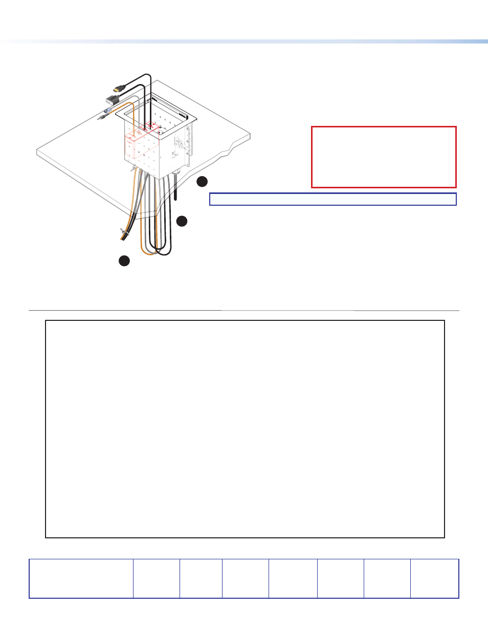
Routing and Connecting Cables
Lower the Cable Cubby into the hole to test the fit.
If necessary, carefully enlarge the opening.
Remove the plastic strips and
film on the surface of the
Cable Cubby.
Ensure that the
side clamps are
seated against the
enclosure.
Secure cables with zip ties to the rectangular
holes in the rear of the Cable Cubby.
For cable pass-through applications, allow at least 36 inches (0.9 m)
of cable loop for each cable.
Connect cables to the AV system
and connect the AC power cord.
Rotate the side clamp
outward and ensure that
the lever is down.
Slide the clamp all the way
up against the bottom of
the table.
Ensure the Cable Cubby
is firmly seated in the table.
Raise the lever to secure
the Cable Cubby.
Lever
1
2
3
2
1
3
1
2
3
CAUTION:
Risk of Electric Shock.
This equipment must be grounded.
ATTENTION:
Risque de choc électrique.
Cet équipement doit être fixé au sol.
NOTE:
Ensure that there is no tension on the power cable.