Extron Electronics DA RGB_YUV Series User Manual
Page 9
DA RGB/YUV Distribution Amplifiers • Installation and Operation
DA RGB/YUV Distribution Amplifiers • Installation and Operation
Installation and Operation, cont’d
2-5
2-4
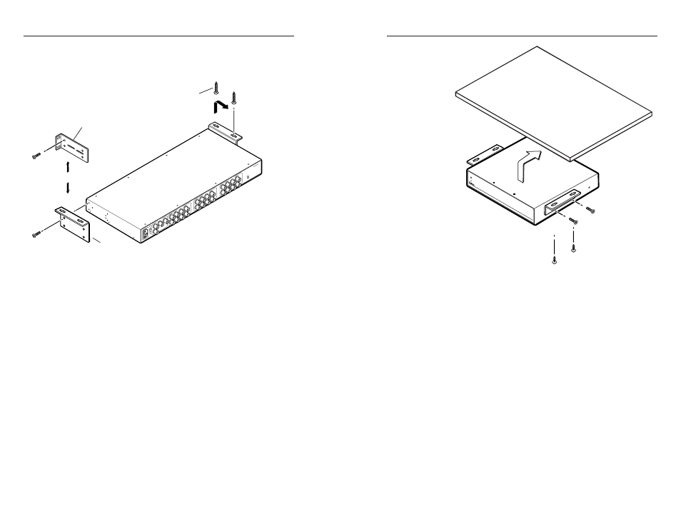
Rack mounting the DA4 and DA6
1
.
Attach the rack mount brackets to the DA with the eight
provided #8 machine screws (figure 2-2).
#8 Screw (4 Plcs)
Each Side
Mounting Screws (2 Plcs)
Each Side
Rack-mount
Bracket
Table/
Wall-mount
Bracket
Drill pilot holes
3/32” (2.4 mm) diam
1/4” (6.3 mm) deep
or
IN
PU
T
Y
DIG
ITA
L
AUD
IO
R-Y
B-Y
10
0-2
40
V
1.3
A
50
-60
Hz
DA
6 Y
UV
A
OU
TP
UT
1
OU
TP
UT
2
DIG
ITAL
AU
DIO
DIG
ITA
L
AU
DIO
Y
R-Y
B-Y
Y
R-Y
B-Y
DIG
ITA
L
AU
DIO
DIG
ITA
L
AUD
IO
Y
R-Y
B-Y
Y
R-Y
B-Y
OU
TP
UT
3
OU
TP
UT
4
DIG
ITA
L
AU
DIO
DIG
ITA
L
AU
DIO
Y
R-Y
B-Y
Y
R-Y
B-Y
OU
TP
UT
5
OU
TP
UT
6
AC
/DC
SPA
RE
ON
Figure 2-2 — Rack mounting a DA4 or DA6
2
.
Insert the DA into the rack, aligning the holes in the
mounting bracket with those of the rack.
3
.
Secure the DA to the rack using the supplied machine
screws.
Under-furniture mounting the DA
The DAs can be mounted under a table or other horizontal
surface. The DA2 RGBHV requires an optional Extron MBU 125
under-desk mounting kit (part #70-077-01). The DA4 and DA6
models require the included table/wall mount bracket. Mount
the DA under a desk or table as follows:
1
.
Secure the under-desk mounting brackets to the DA with
the four (DA2) or eight (DA 4 and DA6) machine screws
provided in the mounting kit (figure 2-2 for the DA4 and
DA 6 or figure 2-3 for the DA 2).
2
.
Hold the DA with attached brackets against the underside
of the desk or other furniture. Mark the location of holes
for screws on the desk.
DA
RG
B/Y
UV
SE
RIE
S
W
IDE
BA
ND
D
IS
TR
IB
UT
IO
N A
MP
LIF
IE
R
Figure 2-3 — Under-furniture mounting
3
.
Drill 1/4" (6.4 mm) deep, 3/32" (2 mm) diameter pilot
holes in the table or desk at the marked screw locations
from the underside or inside (the concealed side) of the
furniture, where the DA will be located.
4
.
Insert the four wood screws into the pilot holes. Fasten
each screw into the installation surface until just less than
1/4" of the screw head protrudes.
5
.
Align the installed screws with the slots in the mounting
brackets, and place the DA against the surface, with the
screws through the bracket slots.
6
.
Slide the DA slightly forward or back, then tighten all four
screws to fasten it in place.