Extron Electronics DA RGB_YUV Series User Manual
Page 5
DA RGB/YUV Distribution Amplifiers • Quick Start Guide
Quick Start Guide — DA RGB/YUV, cont’d
i
DA RGB/YUV Distribution Amplifiers • Table of Contents
Chapter 1 • Introduction
.......................................................... 1-1
About the Distribution Amplifiers
............................... 1-2
Chapter 2 • Installation and Operation
......................... 2-1
Installation Overview
.......................................................... 2-2
Mounting Options
................................................................. 2-2
Rack mounting the DA ............................................................. 2-2
Rack mounting the DA2
.................................................... 2-2
Rack mounting the DA4 and DA6
...................................... 2-4
Under-furniture mounting the DA ......................................... 2-4
Through-furniture mounting the DA ................................... 2-6
Rear Panel Connections
...................................................... 2-7
Input connections .................................................................. 2-8
Output connections ............................................................... 2-9
Mute connection ................................................................. 2-10
Power connection ................................................................ 2-10
Controls and Indicators
.................................................... 2-11
Operation and Troubleshooting
.................................. 2-12
If the image does not appear or is not displayed correctly . 2-12
Appendix A • Reference Information
............................ A-1
Specifications
......................................................................... A-2
Part Numbers
.......................................................................... A-6
DA part numbers .................................................................. A-6
Included parts ....................................................................... A-6
Optional accessories ............................................................. A-6
Bulk cable .............................................................................. A-6
Assorted connectors ............................................................. A-7
Pre-cut cables ........................................................................ A-7
Table of Contents
68-512-01 Rev. C
06 06
All trademarks mentioned in this manual are the properties of their respective owners.
RGBHV
video
RGBS
video
RGsB,
RsGsBs
(or component
video)
Component
video (or
RGBS, RGsB,
RsGsBs
DA6 YUV A
DA2 RGBHV, DA4 RGBHV, DA6 RGBHV
H
H/V
V
R
G
B
H
H/V
V
R
G
B
H
H/V
V
R
G
B
DIGITAL
AUDIO
Y
R-Y
B-Y
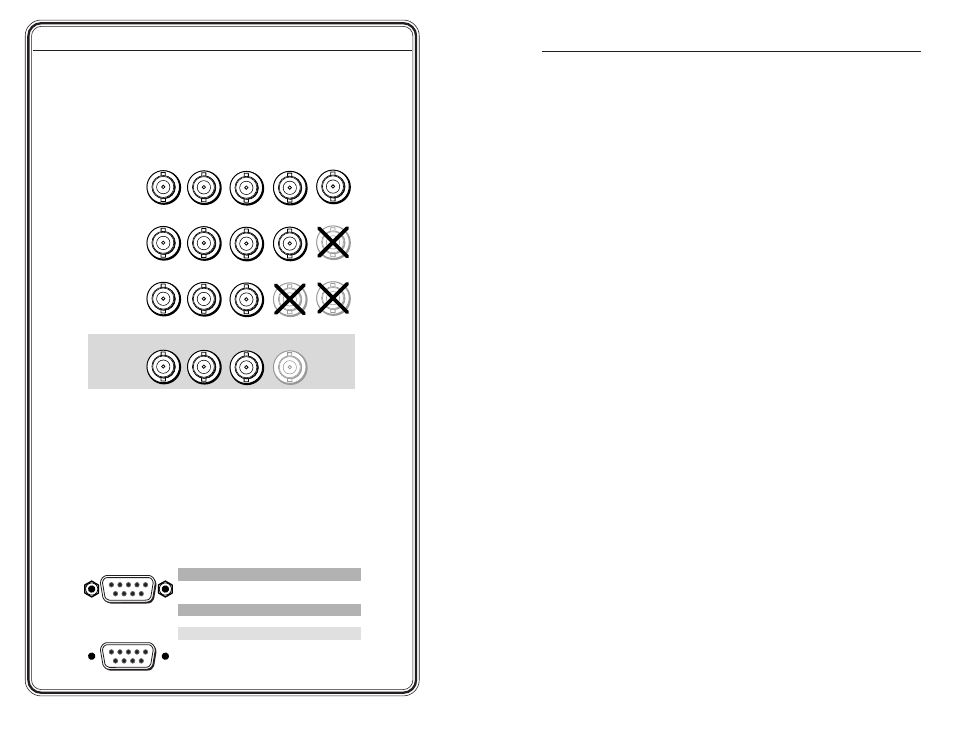
Step 5
Video outputs
— Connect RGB or component video displays or
other devices as shown. You can use a DA6 YUV A to buffer RGsB or
RsGsBs video. You can also output RGBS video by connecting the
composite sync (S) plane on the digital audio BNC to the composite
sync (S) input of the video displays or other devices.
Step 6
(DA6 YUV A only) Digital audio outputs
— Connect digital audio
devices to the output Digital Audio connectors. If you are using the
DA to buffer RGBS video, connect this connector to the composite
sync (S) input of the video displays or other devices in place of the
digital audio.
Mute function
Mute connector (all, excluding DA6 YUV A) —
Each active pin of
the 9-pin D connector is assigned to one of the DA’s outputs (pin 2 is
assigned to all DA outputs). Short and latch an active pin to ground
to mute that output’s R, G, and B video planes.
Pin
Contact closure
Function
1
Out #1
Mute output #1
2
—
Out all
Mute all outputs
3
Not used
4
Out #2
Mute output #2
5
Gnd
Ground
6
Out #3
Out #4
Out #5
Out #6
Mute output #3
Mute output #6
Mute output #4
Mute output #5
7
8
9
Female
5
1
9
6
Male
1
5
6
9
QS-2