Installation and operation, cont’d, Controls and indicators, Mute connection – Extron Electronics DA RGB_YUV Series User Manual
Page 12: Power connection
DA RGB/YUV Distribution Amplifiers • Installation and Operation
DA RGB/YUV Distribution Amplifiers • Installation and Operation
Installation and Operation, cont’d
4
Digital audio output (DA6 YUV A only)
— Connect digital
audio devices to these female BNC connectors for each audio
output.
If you are using the DA to buffer RGBS video, connect this
connector to the composite sync (S) input of the video displays
or other devices.
Mute connection
5
Mute connector (all, excluding DA6 YUV A) —
The Mute
connector provides a way to mute (blank) any or all outputs.
Each active pin of the 9-pin D connector is assigned to one of the
DA’s outputs (pin 2 is assigned to all DA outputs) (figure 2-10).
When you short and latch an active pin or pins to ground, the
DA mutes the associated output(s).
Only the R, G, and B video signals are muted. The H
and V video signals are still distributed.
Pin
Contact closure
Function
1
Out #1
Mute output #1
2
—
Out all
Mute all outputs
3
Not used
4
Out #2
Mute output #2
5
Gnd
Ground
6
Out #3
Out #4
Out #5
Out #6
Mute output #3
Mute output #6
Mute output #4
Mute output #5
7
8
9
Female
5
1
9
6
Male
1
5
6
9
Figure 2-10 — Mute connector and pinout
Pins associated with an output number greater than what is
available for a specific DA have no function in smaller DAs. For
example, pin 6 (output 3) through pin 9 (output 6) have no
function on the DA2 RGBHV.
Power connection
6
AC power connector —
Plug a standard IEC power cord into
this connector to connect the DA to a 100VAC to 240VAC,
50 or 60 Hz power source.
2-10
AC/DC
GAIN/PEAK
ON
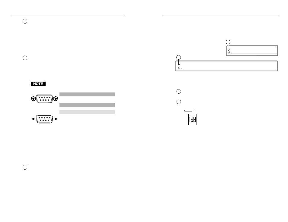
Controls and Indicators
Each of the DAs has power LEDs on both the front panels
(figure 2-11) and rear panels (figure 2-5 through figure 2-7) and
two DIP switch controls on the rear panel.
DA RGB/YUV SERIES
WIDEBAND DISTRIBUTION AMPLIFIER
DA RGB/YUV SERIES
DA2 RGBHV
WIDEBAND DISTRIBUTION AMPLIFIER
DA4 RGBHV, DA6 RGBHV, DA6 YUV A
7
7
Figure 2-11 — DA RGB/YUV series front
panels
7
Power LEDs —
When lit, the front and rear power LEDs
indicate that power is applied to the DA.
8
DIP switches —
The DAs have two rear panel DIP switches;
one to turn gain and peaking on and off (spare on
the DA6 YUV A
) and one to turn AC coupling on
and off.
Gain/Peak switch (DA2 RGBHV, DA4 RGBHV, and
DA6 RGBHV only)
— Turn this switch on and off while
viewing the displayed image to set the level that provides
the best picture quality.
On (up)
— Applies gain and peaking. Use this position
for long cable runs (up to 200 feet using
Extron MHR cable).
Off (down)
— No gain or peaking. Use this position for
short cable runs.
AC/DC switch
— Input coupling.
On (up)
— Use this position when the signal source has a
high DC offset.
Off (down)
— This is the default position for the best
picture quality.
2-11