Installation, cont’d, Video loopback connections, Rs-232 or contact closure connection – Extron Electronics CD 900 User Manual
Page 8: Cd900 system 8 plus
CD 900 Decoder • Installation
CD 900 Decoder • Installation
Installation, cont’d
2-4
that the H/HV/SOG is in the HV position (see “Setting Up
the CD 900/Rear Panel Controls” in chapter 3).
H
SOG
H/V
H/HV
V
R/P
R
G
B/P
B
Figure 4 — RGBHV output connections
SOG
H/V
H/HV
V
H
R/P
R
G
B/P
B
Figure 5 — RGBS output connections
RGsB video connection
— For RGsB video, connect to the
three BNC connectors shown in figure 6. Ensure the
RGB/Component DIP switch is in the right position and
that the H/HV/SOG is in the SOG position (see “Setting
Up the CD 900/Rear Panel Controls” in chapter 4).
H
SOG
H/V
H/HV
V
R/P
R
G
B/P
B
Figure 6 — RGsB and component video output
connections
Component video connection
— For Y, P
B
, P
R
component
video, connect to the three BNC connectors shown in
figure 6. Ensure the RGB/Component DIP switch is in the
left position and that the H/HV/SOG is in the SOG
position (see “Setting Up the CD 900/Rear Panel Controls”
in chapter 3).
RS-232 or contact closure connection
4
RS-232/Remote connector
— Connect a host device, such as a
computer or touch control panel, or a
remote contact closure device to the
CD 900 via this 9-pin D connector for
remote control using the Simple
Instruction Set™ (SIS), the Extron
graphical control program for
Windows, or a contact closure device.
See chapter 4, “Remote Control” for definitions of the SIS
commands, details on how to install and use the control
software, and information on how to make a remote contact
closure device.
Female
5
1
9
6
Male
1
5
6
9
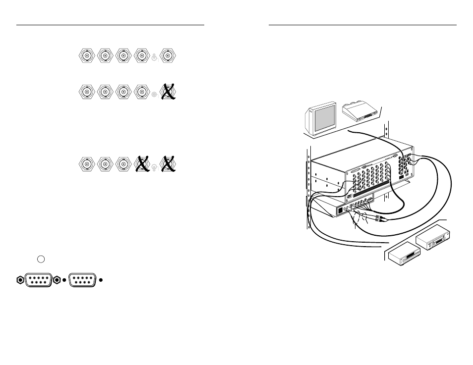
Video Loopback Connections
The CD 900 can be used with a system switcher in video
loopback (VLB) mode. Details of this operation are included in
Extron’s System 8/10 Plus switcher manual, part #68-078-01.
The composite video, and/or the S-video outputs from the
system switcher become the inputs for the CD 900. The RGB or
component output from the CD 900 then connects to a special
input on the system switcher. Figure 7 shows a typical video
loopback hookup.
CD900
System 8 PLUS
DVD player
Composite video sources
Composite
video output
S-video
output
S-video sources
SVHS - BNC adapter
part #26-353-01
Inputs
Output
VCR
Figure 7 — Typical video loopback application
The CD 900 decodes all composite video or S-video signals that
enter the system switcher, saving the cost of separate decoders
for each source.
2-5