Setup and operation, cont’d, Operation, Selecting an input – Extron Electronics CD 900 User Manual
Page 11: Picture controls
CD 900 Decoder • Setup and Operation
CD 900 Decoder • Setup and Operation
Setup and Operation, cont’d
CD 900
MIN
MAX
COLOR
TINT
CONTRAST
H SHIFT
1
2
PICTURE CONTROLS
INPUT SELECTION
NTSC
PAL
SECAM
NTSC 4.43
3
4
6
5
12
7
11
8
9
10
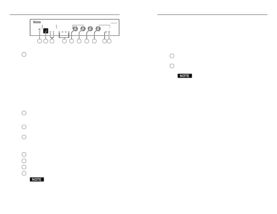
Figure 9 — Front panel controls and indicators
3
Power LED
— The Power LED lights to indicate power is on. If
AC voltage is available, power is on. When power is first
applied, all front panel LEDs flash to indicate that the power up
sequence was accomplished satisfactorily.
Selecting an input
Press the Input Selection button (4) on the front panel to select
either composite video (LED 1) or S-video (LED 2). An input
image should now appear on the display device. If it does not,
check the input source and connections.
The CD 900’s memory stores two sets of control settings: one set
is for the S-video and one for the composite video input. Each
set includes current values for color, tint, contrast and
horizontal shift settings.
4
Input Selection button
— Pushing the Input Selection button
toggles between input 1 (composite video) and input 2
(S-video).
5
Input 1 and Input 2 LEDs
— These LEDs indicate the selected
input.
6
Input signal format LEDs
— One of four LEDs indicates the
incoming signal type: NTSC (3.58), PAL, SECAM or NTSC 4.43.
Picture controls
7
Color adjustment
— Color intensity adjustment control.
8
Tint adjustment
— Tint (hue) adjustment control.
9
Contrast adjustment
— Contrast and brightness control.
10
H Shift adjustment
— Horizontal centering control.
1. The picture control adjustments (Color, Tint,
Contrast, and H Shift) have no mechanical limits.
When the minimum or maximum limit is reached the
Min or Max LED blinks.
2. The Min and Max LEDs both blink once when a
picture control adjustment is turned through the
default value.
3. The picture control adjustments increase or decrease
a value that is stored in nonvolatile memory. The
memory stores two sets of four values, one set for
each input. Each set includes the current values for
the four picture control adjustments.
11
Min LED
— Blinks to indicate the minimum limit has been
reached for the picture control being adjusted.
12
Max LED
— Blinks to indicate the maximum limit has been
reached for the picture control being adjusted.
1. There is no indication that a picture control
adjustment is at its limit unless its adjustment knob
is being turned.
2. When the CD 900 is in executive mode (see “Setting
Up the CD 900/Rear Panel Controls”), the picture
controls are disabled and the Min and Max LEDs
both light.
3. If picture control is not available for the video type in
use (such the Tint control when the input type is
PAL), the Min and Max LEDs blink continuously
when the unavailable control knob is turned.
Operation
Plug in all system components and turn on the input devices
(DVD player, laserdisc player, DSS receiver, etc.) and the output
device. Set the input devices to output video in accordance with
their own operating instructions. The image should appear on
the screen.
For each input, adjust the picture controls (Color, Tint, Contrast,
and H Shift) for the best possible image.
To output RGB video
1
.
Set the RGB/component DIP switch to the on/left
position.
2
.
Set the H/HV/SOG switch to the correct position for the
video format (see “(2) H/HV/SOG switch” on page 3-3.
3-5
3-4
.