Installation, Installation, cont’d, Rear panel cabling – Extron Electronics CD 900 User Manual
Page 7: Installation overview, Mounting the cd 900, Power connection, Signal input and output connections
CD 900 Decoder • Installation
CD 900 Decoder • Installation
Installation, cont’d
2-3
b
.
Mount the CD 900 on the rack shelf, using two
4-40 x 1/8 screws in opposite (diagonal) corners to
secure the case to the shelf.
2
.
If desired, attach a false front panel, or a second ½-rack-
width device to the other side of the shelf.
3
.
Attach the rack shelf to the rack using four 10-32 x ¾” bolts
and four #10 beveled dress washers.
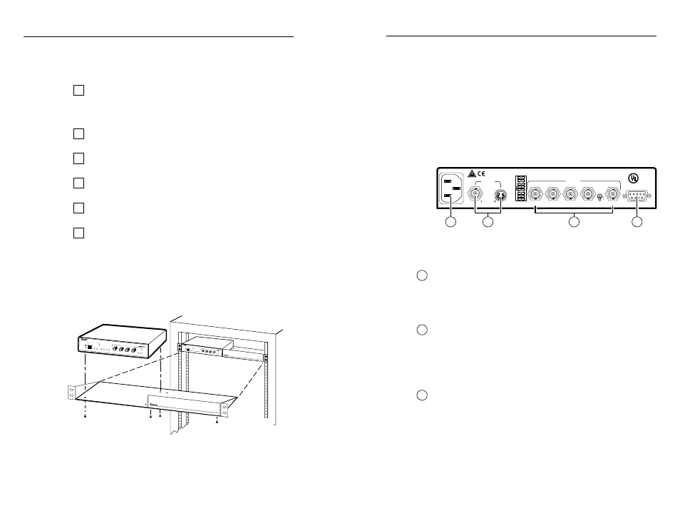
Rear Panel Cabling
All connectors are on the rear panel. Figure 3 shows the cable
connections on the rear panel of the CD 900 decoder.
SERR REM
H+
RGB/COMP
SPARE
SPARE
AUTO SW
LISTED
1T23
I.T.E.
US
C
V+
X MODE
H
SOG
H/V
R/P
R
G
B/P
B
H/HV
V
OUTPUT
RS-232
INPUTS
REMOTE
100-240VAC~50/60Hz
0.1A MAX
1
4
3
2
Figure 3 — Rear panel cabling
Power connection
1
AC power connector
— Plug a standard IEC power cord into
this connector to connect the CD 900 to a 100 to 240VAC, 50 Hz
or 60 Hz power source.
Signal input and output connections
2
Input connectors
Input 1, composite video connector
— Connect composite
video to this BNC connector.
Input 2, S-video connector
— Connect S-video to this 4-pin
mini DIN connector.
3
Output connectors
RGBHV video connection
— For RGBHV video, connect
to all five BNC connectors as show in figure 4. Ensure the
RGB/Component DIP switch is in the right position and
that the H/HV/SOG is in the H position (see “Setting Up
the CD 900/Rear Panel Controls” in chapter 3).
RGBS video connection
— For RGBS video, connect to the
four BNC connectors shown in figure 5. Ensure the
RGB/Component DIP switch is in the right position and
Installation
Installation Overview
To install and set up the CD 900 quad-standard decoder for
operation, follow these steps:
1
Turn off all of the equipment. Ensure that the video
sources (DVD players, laserdisc players, VCRs, satellite
receivers, or other devices) and the output display are all
turned off and disconnected from the power source.
2
Mount the switcher. See “Mounting the CD 900” in this
chapter.
3
Attach the cables. See “Rear Panel Cabling” in this
chapter.
4
Connect power cords and turn on the display device and
the input devices, in that order.
5
Set the rear panel DIP and sync switches. See “Setting up
the CD 900/Rear Panel Controls” in chapter 3.
6
Select an input and adjust the picture controls on the front
panel. See “Front Panel Controls and Indicators” in
chapter 3.
Mounting the CD 900
1
.
For optional rack mounting, mount the CD 900 on the left
or right side of a 19" 1U Universal Rack Shelf (Extron
part #60-190-01) (figure 2).
4-40 X 1/8 Screws
Use 2 Mounting Holes
on Opposite Corners
False Front Panel
Uses 2 Front Holes Only
CD 900
MIN
MAX
COLOR
TINT
CONTRAST
H SHIFT
1
2
PICTURE CONTRO
LS
INPUT SELECTION
NTSC
PA
L
SEC
AM
NTSC 4.43
CD 900
MIN
MAX
COLOR
TINT
CONTRAST
H SHIFT
1
2
PICTURE CON
TROLS
INPUT SELECT
ION
NTSC
PAL
SECAM
NTSC 4.43
Figure 2 — Rack mounting the CD 900
a
.
If feet were previously installed on the bottom of the
case, remove them.
2-2