Setup and operation, Setup and operation, cont’d, Setting up the cd 900/rear panel controls – Extron Electronics CD 900 User Manual
Page 10: Front panel controls and indicators
CD 900 Decoder • Setup and Operation
CD 900 Decoder • Setup and Operation
Setup and Operation, cont’d
Setup and Operation
3-2
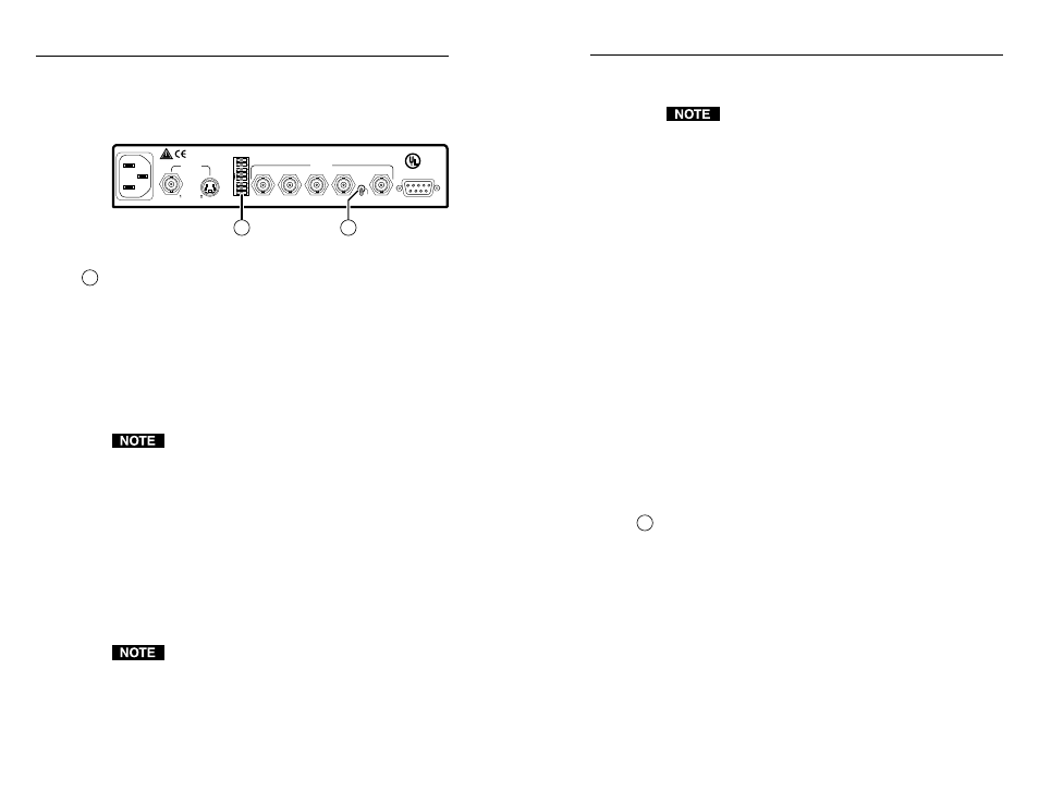
Setting Up the CD 900/Rear Panel Controls
Figure 8 shows the switches on the rear panel of the CD 900.
Refer to figure 8 and the following descriptions of the rear panel
switches to set up the CD 900.
SERR REM
H+
RGB/COMP
SPARE
SPARE
AUTO SW
LISTED
1T23
I.T.E.
US
C
V+
X MODE
H
SOG
H/V
R/P
R
G
B/P
B
H/HV
V
OUTPUT
RS-232
INPUTS
REMOTE
100-240VAC~50/60Hz
0.1A MAX
1
2
Figure 8 — Rear panel switches
1
DIP switches
— The functions of the DIP switches follow. The
DIP switches are numbered 1 through 8 from top to bottom.
On the CD 900, slide or rock the rear panel DIP switches to the
left (toward the name) to activate or enable the function, or to
the right (away) to disable the function.
1
AUTO SW (auto switch mode) —
Enabled
— When on/left, the input with a video signal
present is selected automatically. If video is present on
both inputs, input two (S-video) is selected.
Auto-switching does not function in SECAM.
Disabled
— When off/right, the input must be selected
manually, via the front panel Input Selection button or
through the RS-232/Remote connector.
2 and 3 Spare
— Not used.
4 RGB/Component
—
Enabled
— When on/left, the CD 900 outputs RGB video.
The sync format is determined by the position of the
H/HV/SOG switch.
Disabled
— When off/right, the CD 900 outputs
component video (Y, P
B
, P
R
) on the R, G, and B BNCs.
To output component video, the H/HV/SOG switch
must also be in the SOG position.
5 SERR (serration pulse removal)
—
Enabled
— When on/left, serration pulses are removed
from the output vertical sync pulse. LCD, DLPs and
plasma displays must have the serration pulses removed
from the sync signal in order to display properly.
Flagging or bending at the top of the video image is a
sign that the serration pulses should be removed.
Disabled
— When off/right, serration pulses are passed
along with the vertical sync pulse.
6 H+ (horizontal sync polarity pulse)
—
Enabled
— When on/left, the horizontal sync polarity is
positive.
Disabled
— When off/right, the horizontal sync polarity is
negative.
7 V+ (vertical sync polarity pulse)
—
Enabled
— When on/left, the vertical sync polarity is
positive.
Disabled
— When off/right, the vertical sync polarity is
negative.
8 X MODE (executive mode)
—
Enabled
— When on/left, the front panel picture control
adjustments (Color, Tint, Contrast, and H Shift) are locked
out. These picture controls are still accessible via RS-232
control. The front panel Min and Max LEDs light together
to indicate that executive mode is enabled.
Disabled
— When off/right, all front panel operations are
enabled.
2
H/HV/SOG switch
— This switch selects the sync signal that is
output on the output H BNC.
H position
— Horizontal sync only is output on the H BNC.
Vertical sync is output on the V BNC. Use this switch position
for RGBHV video.
HV position
— Composite (horizontal and vertical) sync is
output on the H BNC. Use this switch position for RGBS video.
SOG position
— Sync is on the green signal and is not output
on the H BNC. Use this switch position for RGsB or for
component video.
Front Panel Controls and Indicators
Figure 9 shows the controls and indicators on the front panel of
the CD 900 quad-standard decoder.
3-3