Controls and installation, Controls and installation, cont’d, Front and rear panels – Extron Electronics CD 800 User Manual
Page 7: Front panel features, Rear panel features
CD 800 Controls and Installation
CD 800 Controls and Installation
Controls and Installation, cont’d
Controls and Installation
2-3
Front and Rear Panels
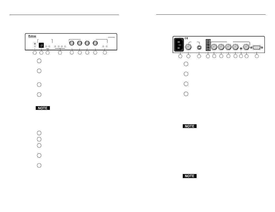
Front panel features
1
Power indicator LED —
Lights to indicate the unit is
receiving power.
2
Input selection button —
Selects either the
composite video input source or the S-video input
source.
3
Input selection LEDs —
Indicate the selected video
input. LED 1: composite video. LED 2: S-video.
4
Input signal format LEDs —
Light to indicate the
incoming signal type: NTSC 3.58, PAL, SECAM, or
NTSC 4.43.
The CD 800’s memory stores two sets of control
settings: one for S-video input, and one for
composite video input. For the next four controls,
all front panel settings are saved automatically to
memory for each input. When using RS-232, you
can save the settings to a file for future use.
5
Color knob —
Adjusts the displayed color.
6
Tint knob —
Adjusts the tint (hue) level.
7
Contrast knob —
Increases or decreases the contrast
(white level).
8
H-shift knob —
Shifts the image left or right to
center it on the display screen.
9
Min/Max LEDs —
Light when a picture control has
been adjusted to its minimum (Min) or maximum
(Max) limit. The LED continues to blink if the knob
is rotated past the limit. Both LEDs blink once,
simultaneously, when a control passes through its
default value.
If a control does not apply to the video format being
used, such as if the tint control knob is rotated when
the input signal is PAL video, both LEDs blink
2-2
simultaneously and continuously as the control knob
is rotated.
Rear panel features
1
IEC AC power connector —
Use this with any power
source from 100VAC to 240VAC, 50 Hz or 60 Hz.
2
Input 1 —
Connect a composite video source to this
BNC input connector.
3
Input 2 —
Connect an S-video source to this 4-pin
mini-DIN female connector.
4
DIP switches —
These eight DIP switches, numbered
1 to 8 from top to bottom, function as follows:
1 — AUTO SW (auto-switching)
On — The CD 800 automatically switches to
the input that has a sync signal present.
If sync signals are present at both inputs,
S-video is selected as the default input.
Auto-switching is not available in SECAM.
Off — You must select the input from the front
panel button, through an RS-232
program, or by a contact closure remote
control device.
2, 3, and 4 — Spare
(no function)
5 — SERR (serration pulse removal)
Digital displays, such as LCD, DLP, and plasma
displays, must have the serration pulses
removed from the sync signal in order to display
images properly.
Flagging or bending at the top of the video image is
a sign that the serration pulses should be removed.
On — Left: Serration pulses are removed from
the vertical sync interval.
Off — Right: Serration pulses pass through to
the output.
CD 800
MIN
MAX
COLOR
TINT
CONTRAST
H SHIFT
1
2
PICTURE CONTROLS
INPUT SELECTION
NTSC
PAL
SECAM
NTSC 4.43
1
2
3
4
5
6
7
8
9
H
SOG
H/V
R
G
B
H/HV
V
OUTPUT
1
2
RS-232
INPUTS
REMOTE
100-240VAC 50/60Hz
0.1A MAX
SERR REM
H+
SPARE
SPARE
SPARE
AUTO SW
V+
X MODE
1
2
3
4
5
6
7
8
9
10
11