Appendix, Specifications – Extron Electronics CD 800 User Manual
Page 13
CD 800 Remote Operation
Remote Operation, cont’d
CD 800
A
Appendix
Specifications
3-6
•
From within the Signal Enhancement Products
Control Program, press the F1 key.
•
From the Extron Electronics program folder or group,
double-click on the Signal Enhancement
Products Help icon.
Remote Contact Closure
The RS-232/Remote connector provides a way to switch
inputs on the CD 800 from a remote contact closure device.
This is made possible through pins that are not used by the
RS-232 interface. The contact closure pin assignments are
shown below.
Pin
Description
1
No connection
6
Input #1
2
Transmit data
7
Input #2
3
Receive data
8
Tally #1
4
No connection
9
Tally #2
5
Signal ground
To select a different input number through this connector,
momentarily short the pin for the desired input number (#)
to logic ground (pin 5). To force one of the two inputs to be
selected continuously, leave the short to logic ground in
place. This will override front panel input selection.
The tally pins can be used for remote indication of the
selected input. Tally #1 or tally #2 (pins 8 and 9) indicate
the selected input # with a logic low (0 volts). The tally
pins are normally at logic high (5 volts).
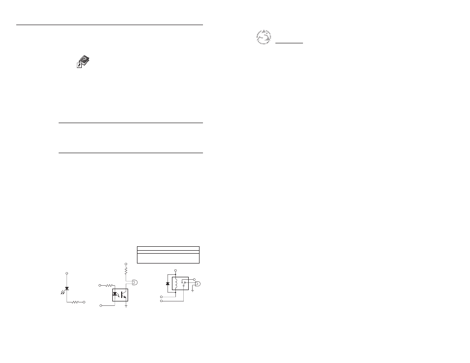
You can use the schematics below as a guide to design and
build indicator circuits for the tally pins. An external
voltage source is required to drive these indicator circuits.
External +5VDC
Tally Pin
LED
330 Ohm
External +5VDC
External Power
External Power
Tally Pin
Tally Pin
Resistor value
depends on current
requirement of lamp
330 Ohm
N/C
1N916
External +5VDC
LED Indicator Circuit
Incandescent Lamp Circuit
Using an Opto-Isolator & External Power
Incandescent Lamp Circuit
Using a Relay & External Power
RECOMMENDED RELAYS
MANUFACTURER GENERAL
LOW CURRENT
Aromat
DS2
TQ
ITT/Panasonic
R-Z-5C
A5W
Omron
G5Y
G6H