Power up sequence, Output lights, Periodic inspection – Bell & Gossett P86271B Variable Speed NRF-VS Control with setpoint or external signal follower User Manual
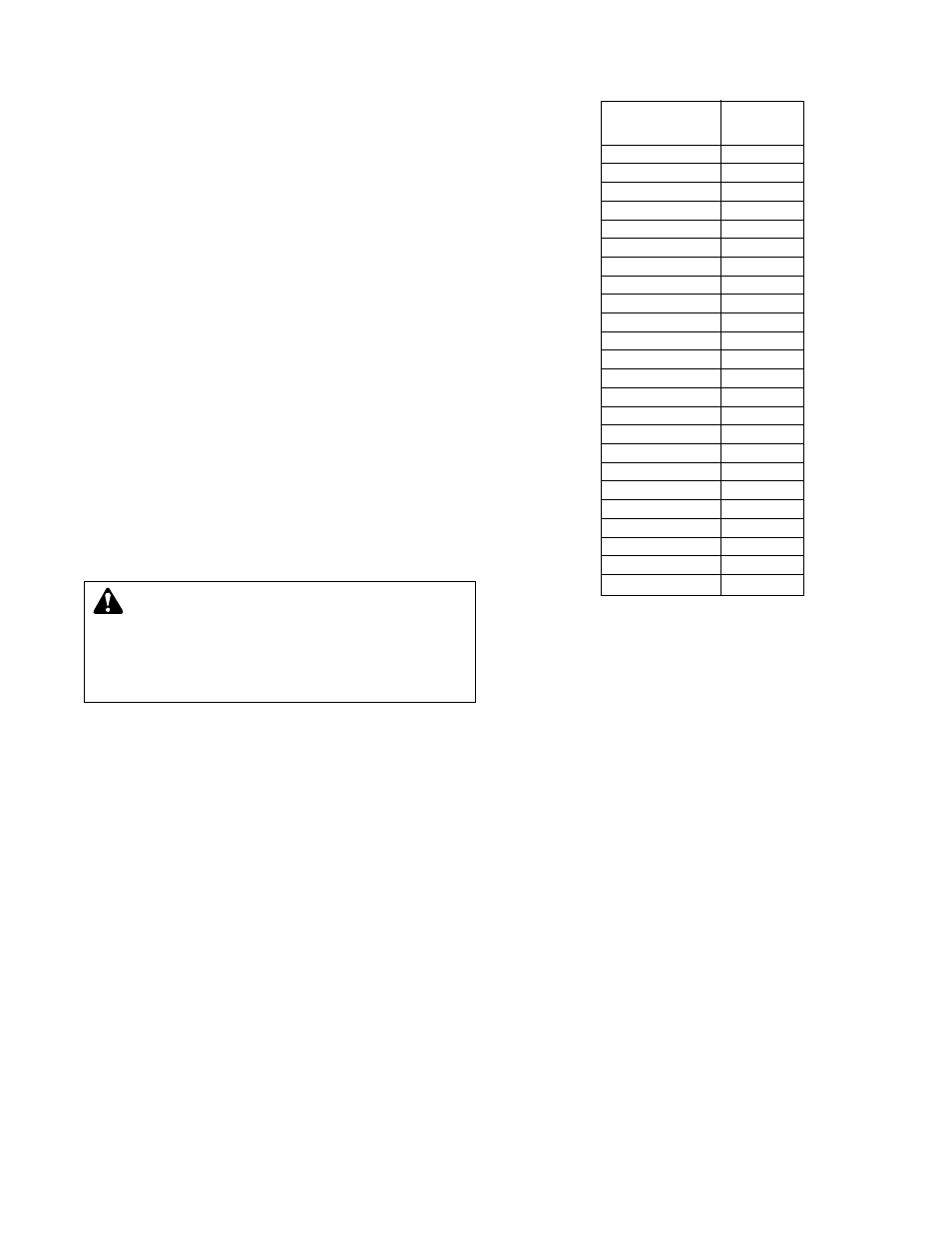
Page 7: Tempera ture sensor chart
POWER UP
SEQUENCE
At initial power up, the NRF-VS
will run at full speed for 5
seconds. It will then run at low speed for 5 seconds, before
adjusting to the appropriate speed. Monitor the pump at initial
power up. If the pump does not operate as indicated above,
the Gain (DIP Switch 4) can be adjusted to On (Fast) to
increase the minimum power setting.
OUTPUT LIGHTS
The NRF-VS cover has 6 LED lights to indicate operation and
faulty status.
THE GREEN OUTPUT LIGHT
Represents power to the NRF-VS. When constantly On, the
control is powered.
THE RED OUTPUT LIGHTS
Represent pump speed in increments of 20%. If only one Red
light is on, the pump speed is equal to or below 20%. If 2 Red
lights are On, the pump speed is equal to or below 40%.
When 3 Red lights are On, the pump speed is equal to or
below 60%. When 4 Red lights are On, the pump speed is
equal to or below 80%. When all Red lights are On, the pump
is running from 80% to full speed.
FLASHING LIGHTS
•
This indicates an error in the input signal. If NRF-VS is set
to 4-20mA/2-10V, the signal must be below 0.5mA or
0.25V. Check input signal and wiring.
• If NRF-VS is set to Set Point, the sensor has fault status,
either shorted or opened. Check sensor wires and Ohm
reading against sensor temperature chart.
PERIODIC
INSPECTION
Bell &
Gossett products are designed to provide years of
trouble free service. It is recommended that periodic inspec-
tions be made to check for potential problems with the pump
and control. If any leakage or evidence of leakage is present,
repair or replace the unit.
TEMPERATURE
Value
(in Degrees ºF)
(in 0hms)
30
17264
35
14985
40
13040
45
11374
50
9944
55
8714
60
7653
70
5941
80
4649
90
3667
100
2914
110
2332
120
1879
130
1524
140
1243
150
1021
160
842
170
699
180
583
190
489
200
412
210
349
220
297
230
253
WARNING: The NRF-VS is an operating control only.
The boiler must have all safety and limit controls
required by code. It is the responsibility of the installer to
verify that all the safety and limits are working properly
before and after the NRF-VS is installed. Failure to follow
these instructions could result inserious personal injury,
death and/or property damage.
7
TEMPERA
TURE
SENSOR CHART