Piping, Wiring, Nrf-vs control installation – Bell & Gossett P86271B Variable Speed NRF-VS Control with setpoint or external signal follower User Manual
Page 4
PIPING
PIPING OVERVIEW
•
The Primary loop may have mulitple injection loops or other
takeoffs. However, the piping for each injection system
must meet the requirements described below.
• The Injection piping can be installed in either a horizontal or
a vertical configuration.
• The pipe diameters of the Primary and Secondary loops
may differ.
• The Injection Piping diameter must be at least one pipe size
smaller than the smaller of the Primary and Secondary loop
piping. For example, if the Primary loop diameter is 1
1
/
4
"
and the Secondary loop diameter is 1", then the diameter of
the Injection piping must be
3
/
4
" or smaller.
• The Injection pump motor must be a fractional B&G NRF,
NBF or SSF permanent split capacitor type pump. (Refer to
operational limits on Page 2 for pump information.) The
Injection pump will control the amount of water pumped
from the Primary loop into the Secondary loop.
• A balancing valve should be installed on the injection return
piping. This helps to balance the system.
• The distance between the injection tees should be as short
as possible. The rule of thumb distance between the tees is
3 times the pipe diameter. For instance, if the pipe diameter
is 1" then the length of straight pipe between the two
injection tees should be 3".
HORIZONTAL PIPING CONFIGURATION
•
The Injection piping can be installed horizontally as shown
in Fig. 2.
• The Injection supply piping should run horizontally from the
Primary to the Secondary loop.
• On the Injection piping it is necessary to install a heat trap
to prevent heat from the Primary loop entering the Secon-
dary loop when the Injection pump is not running.
• The injection piping must drop down vertically at least 18"
and then rise back up vertically at least 18".
VERTICAL PIPING CONFIGURATION
•
The Injection piping can be installed vertically.
• The Primary loop must be at least 18" vertically above the
Secondary loop.
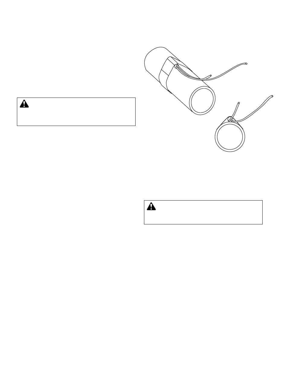
INSTALLING SENSOR
•
In a primary/secondary application, the secondary loop
sensor should be mounted downstream of the inlet loop and
before any major heating units. That will provide the control
a more accurate temperature reading (Refer to Fig. 2.)
• Strap the cylindrical sensor to the pipe as shown in Fig. 3.
• Wrap the pipe and sensor assembly with insulating tape to
insure adequate heat transfer to the sensor.
• The sensor wires can be extended up to 500' from the
controller. If the sensor wires are located in an area with
strong sources of electro-magnetic interference (EMI), the
wires must be run in a grounded metal conduit. Do not run
wires in conduit with line voltage.
WIRING
NOTE:
If the NRF-VS control is already installed on the pump,
skip the NRF-VS control installation section and proceed to
the “wiring the sensors” section.
NRF-VS
CONTROL INSTALLATION
1.
Disconnect the electrical supply to the pump.
2. Remove the screw that holds the steel conduit box cover
to the pump.
3. Remove the conduit box cover. The NRF-VS control
assembly replaces the conduit box cover.
4. Disconnect the black and white motor leads from the
power supply.
5. Position the plastic base for the NRF-VS control
assembly onto the steel conduit box with the warning/
caution label to the rear of the pump.
6. Secure the plastic base to the conduit box with one 8-32
screw provided.
7. Verify that the electrical rating of the NRF-VS control
matches the values shown on the nameplate of the
circulator.
WARNING: ELECTRICAL SHOCK HAZARD
Disconnect and lock out power before making elec-
trical connections. Failure to follow these instructions could
result in serious personal injury or death.
4
CAUTION: The Injection pump and pipe sizing
should be performed by a qualified engineer or
contractor. Failure to follow these instructions could
cause inadequate system performance and/or property
damage.
FIG. 3