Bell & Gossett P86271B Variable Speed NRF-VS Control with setpoint or external signal follower User Manual
Page 6
6
Setpoint (Dip Switch 1=On)
•
The Dial on the NRF-VS allows for set point temperature
adjustment. Use a small screwdriver to turn the dial so that
the arrow lines up with the desired setpoint temperature.
• The pump speed will vary based on the difference between
the secondary loop sensor reading and the set point on the
NRF-VS.
External Signal (Dip Switch 1=Off)
•
Below 4mA or 2V, the pump will fully stop. At 20mA or 10V
the pump will run at full speed.
• The temperature dial is deactivated when control is in the
external signal mode.
Dip Switch 2 (Control Mode Heating or
Cooling) Available with Setpoint Only
2=Off (Heating), 2=On (Cooling)
Default 2=Off
•
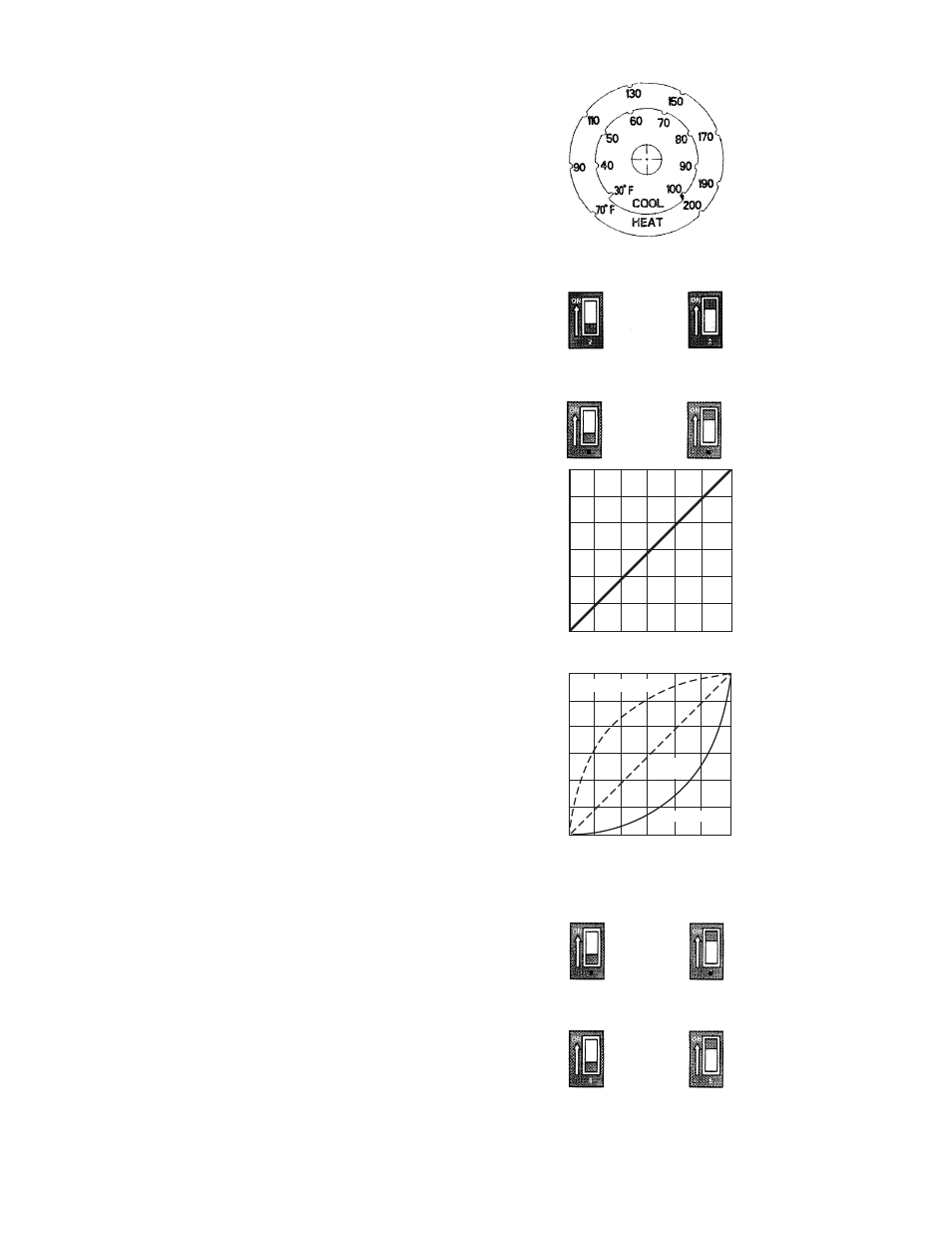
When Heating is selected, the control will increase pump
speed when the loop temperature drops further from the
Setpoint. When loop temperature is higher than the
setpoint, the control will turn off the pump. Refer to the
outer range of 70º-200ºF shown in the scale.
• In Cooling, the control will increase pump speed the higher
the loop temperature increases above the Setpoint. When
the setpoint is reached and maintained, the control will turn
off the pump. Refer to the inner range of 30º-100ºF shown
in the scale.
Dip Switch 3 (Output Mode Linear or Logarithmic)
3=Off (Linear), 3=On (Logarithmic)
Default 3=Off
Linear
(Dip Switch 3=Off)
Linear operation is based on a linear relationship between
percent of flow of the pump and BTU output of the terminal
unit. Typical application is when the pump injects into a
constant circulating loop, which includes the terminal unit.
Logarithmic (Dip Switch 3=On)
Logarithmic operation is based on non-linear relationship
between percent of flow of the pump and BTU output of the
terminal unit. In order to achieve the desired linear output, the
NRF-VS provides a logarithmic output to compensate for the
non-linear terminal output. Typical application is when the
pump injects directly into the terminal unit.
Dip Switch 4 (Gain) Available with Setpoint Only
4=Off (Normal), 4=On (Fast)
Default 4=Off
•
The Gain is how aggressive the control should behave
when loop temperature is far from Setpoint. It governs the
amount of change the control applies to pump speed.
• Normal gain is typically used in applications where the
sensor temperature changes gradually during operation.
• Fast gain is typically used in applications where the sensor
temperature changes rapidly during operation.
Dip Switch 5 (Pump Exercise)
5=On (Exercise), 5=Off (No Exercise)
Default 5=On
•
This Dip Switch regulates if the pump should be exercised
when stayed idle for a long period of time. When set to
Exercise, pump will run at full speed for a period of 10
seconds when left in idle status for a period of 72 hours.
Heating/Cooling Mode Setting
Dip Switch 2 (Setpoint only)
Heating
Cooling
Linear
Logarithmic
Output Mode Setting
DIP Switch 3
3
3
Normal
Fast
Gain Setting
DIP Switch 4
4
4
100%
0%
100%
% of Flow
Linear
BTU Output
100%
0%
100%
% of Flow
Logarithmic
BTU Output
Logarithmic
Desired
Output
Terminal Unit Output
No Exercise
Exercise
10 Sec every
3 idle days
Pump Exercise Setting
DIP Switch 5
Temperature Dial