Opera tion, Design selectio n – Bell & Gossett P86271B Variable Speed NRF-VS Control with setpoint or external signal follower User Manual
Page 3
OPERA
TION
The NRF-VS is designed to control the pump speed on an
injection system allowing the pump to inject a different water
temperature into a secondary loop to regulate its temperature.
It can be used either in heating or cooling applications using a
secondary loop temperature sensor. The sensor reads the
secondary loop temperature allowing the NRF-VS to regulate
the loop temperature by modulating the injection pump speed
accordingly to reach a set point.
A temperature knob mounted on the NRF-VS is used to adjust
the temperature set point either in heating or cooling (see Dip
Switch 2). Dip Switch 1 must be set to ON to activate the Set
Point feature. The sensor must be wired to terminals 2 and 3
when using the setpoint mode.
The NRF-VS can be controlled remotely using an external
signal to replace the set point. This allows for the external
control or system providing the input to change the pump
speed directly. No sensor is required in this setting. The
external input providing either 4-20mA signal or 2-10V signal
must be wired to terminals 1 and 2. The speed of the pump
will vary from full stop below 4mA or 2V to 100% at 20mA or
10V. Dip switch 1 must be set OFF to activate the external
signal feature.
DESIGN SELECTIO
N
To select the correct pump, pipe size and balance valve:
1. Determine the Primary Loop Temperature. This is the
temperature the primary loop will maintain.
2. Determine the Secondary Loop Temperature. This is the
design temperature of the secondary loop. If an outdoor
reset function is being employed, this is the required
temperature of the secondary loop under maximum load.
3. Determine the design temperature drop (
᭝T or delta T) of
the secondary loop. This is the design drop in tem-
perature through the secondary loop. In most radiant
heat applications,
᭝T is 10. Other types of radiation such
as baseboard have a higher design
᭝T.
4. Determine the Maximum Injection Heat Load. This is the
maximum heat requirement of the secondary loop. The
maximum injection heat load is based on the injection
pump running at the highest speed. As the pump speed
is reduced, less heat will be delivered to the secondary
loop.
5. Use the equation below to determine the design injection
flow rate.
Design Injection Flow Rate (GPM) =
Maximum Injection Heat Load (BTU/hr)
500 (T
primary
- T
secondary
+
᭝T
secondary
) (ºF)
6. Use the table below to select the appropriate pump, pipe
size and balance valve.
Design Injection
Injection B&G Circuit
Setter
®
B&G Circuit Setter
®
B&G
Flow Rate (GPM)
Pipe Size
Balance Valve
Valve Setting
Pump
1.5
1
/
2
"
CB-
1
/
2
/ CB-
1
/
2
S
18 / 25
NRF-22
3.5
1
/
2
"
CB-
1
/
2
/ CB-
1
/
2
S
full open / 6
NRF-22
6
3
/
4
"
CB-
3
/
4
/ CB-
3
/
4
S
full open / 12
NRF-22
10
1"
CB-1 / CB-1S
full open / full open
NRF-22
15
1
1
/
4
"
CB-1
1
/
4
/ CB-1
1
/
4
S
5 / 5
NRF-22
Example:
1. Primary Loop Temp: 140ºF
2. Secondary Loop Temp: 100ºF
3. Design temperature drop: 10ºF
4. Maximum injection heat load: 150,000 BTU/hr
5. Calculate Injection flow rate
Design Injection Flow Rate (GPM) =
150,000 (BTU/hr)
=
150,000
= 6 GPM
500 (140 - 100 + 10) (ºF) 25,000
6. Injection Pipe size is
3
/
4
", full open CB-3/4 balancing valve and NRF-22
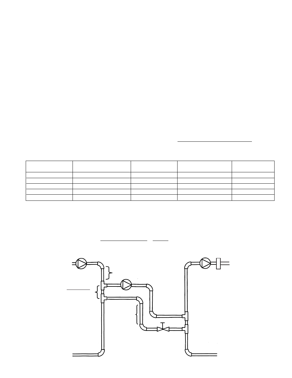
Minimum of 1' of
pipe drop required
to create a thermal
trap
Rule of Thumb
3 pipe diameters
between tees
Minimum of 8 pipe diameters upstream
and 4 pipe diameter downstream of straight
pipe on either side of tees to prevent any
possibility of “jet flow” through the
common piping.
Secondary
Loop
Secondary
Loop Pump
Primary
Loop Pump
Secondary
Loop Sensor
Primary
Loop
Injection Pump
Balance
Valve
3
FIG. 2
Based on (5) feet of pipe, (4) 90
° elbows, (4) tees. Correct pipe and pump size calculation for any application should be performed by a qualified engineer or contractor.