Dip switch settings – Bell & Gossett P86271B Variable Speed NRF-VS Control with setpoint or external signal follower User Manual
Page 5
8.
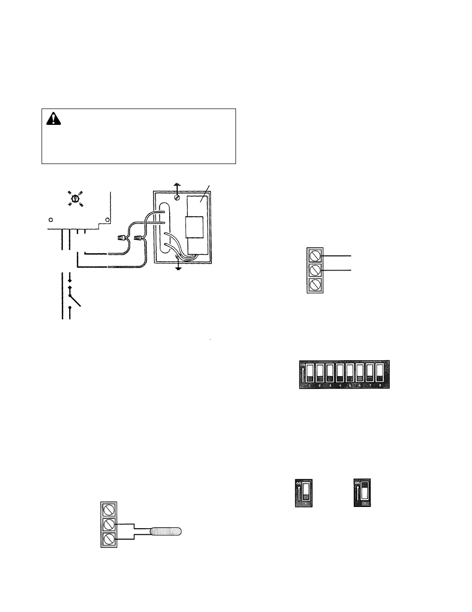
Make the electrical connections according to the wiring
diagram provided (See Fig. 4). Route the power wiring
through one of the
7
/
8
" diameter holes in the steel conduit
box. The control or sensor wiring must pass through the
7
/
8
" diameter hole in the plastic enclosure.
9. Attach 120VAC line voltage to the orange wire extending
from the back of the NRF-VS. Wire the neutral wire to
either of the orange wires extending from the back of the
NRF-VS.
WIRING THE SENSORS FOR SETPOINT CONTROL
•
Sensor terminals are located on the back of the NRF-VS
control board.
• To set the NRF-VS for use with a temperature sensor, set
Dip Switch 1 to On.
• Pass the sensor wiring through the
7
/
8
" hole in the plastic
enclosure. Low voltage wiring must be separated from
power wiring.
• The sensor wires have no polarity. Connect either wire from
the sensor to terminals 2 and 3. (See Fig. 5)
• Sensors are typically installed on the secondary loop. (See
Fig. 2)
• On a sensor failure or short the pump will run at full speed
and LED Lights will blink indicating a fault status.
WIRING THE EXTERNAL SIGNAL INPUT
4-20MA OR 2-10V
•
External signal terminals are located on the back of the
NRF-VS control board. (See Fig. 6).
• To wire the NRF-VS for use with an external signal either
4-20mA or 2-10V, set Dip Switch 1 to Off.
• The NRF-VS DOES NOT source current for the signal. The
current must be supplied by the control or system
supplying the signal.
• Pass the sensor wiring through the
7
/
8
" hole in the plastic
enclosure. Low voltage wiring must be separated from
power wiring.
• Polarity is important when using an External Signal. Always
connect the common to terminal 2 while the signal side is
connected to terminal 1.
• On a signal error the pump will fully stop and LED Lights
will blink indicating a fault status.
• When using 4-20mA input signal, make sure the input
source can supply at least 10V.
• When using 2-10V input signal, make sure the input source
can supply at least 20mA.
DIP SWITCH SETTINGS
Dip Switch 1 (Input Mode 4-20mA/2-10V or Setpoint)
1=Off (4-20mA/2-10V), 1=On (Setpoint)
Default 1=Off
•
This control can vary the pump speed based on either an
External Signal of 4-20mA/2-10V or a Temperature
Setpoint.
WARNING: ELECTRICAL SHOCK HAZARD
Electrical connections are to be made by a qualified
electrician in accordance with all applicable codes, ordi-
nances and good practies. Failure to follow these instruc-
tions could result in serious personal injury, death and/or
property damage.
CAPACITOR
Black
Black
Black
Orange
Orange
Neut
Line
White
White
White
Power Switch
Surge Suppressor
5
Sensor Wiring
12
3
Temperature Sensor
External Signal Wiring
12
3
External Signal
Common
FIG. 4
FIG. 5
FIG. 6
Dip Switches
4-20mA
2-10V
Setpoint
Input Mode Setting
Dip Switch 1