6 change the position of the motor housing, 7 electrical installation, 1 power supply connection – Bell & Gossett P2002548B ecocirc XL High Efficiency Large Wet Rotor Pumps User Manual
Page 9
• Only use the pump thermal shells that are included in the de-
livery. Do not insulate the motor housing, the electronics can
overheat and cause the pump to thermally overload.
• The thermal shells that are included with the pump must only
be used in hot water circulation applications with fluid tem-
perature above 68°F (20°C). The thermal shells are permea-
ble to water vapor.
• If the customer installs the vapor barrier insulation shells for
cold water application, then the pump housing must not be
insulated above the motor flange. The drain opening must
be kept unobstructed in order that the accumulated conden-
sation can run out.
4.6 Change the position of the motor
housing
WARNING:
• Drain the system if possible or close the service valves
on both sides of the pump before disassembling the
pump. The pumped fluid can be pressurized and may
be scalding hot.
• There is the risk of escaping vapor when the motor is
separated from the pump housing.
Electrical Hazard:
Before starting work on the unit, make sure that the unit and
the control panel are isolated from the power supply and
cannot be energized.
CAUTION:
Burn hazard. During operation various surfaces on the unit
will become hot. To avoid burn injury, use heat protective
gloves.
WARNING:
• A strong magnetic field is created when the rotor is re-
moved from or inserted into the motor housing. This
magnetic field can be harmful to pacemaker wearers
and others with medical implants. In addition, the mag-
netic field may attract metal parts to the rotor which can
cause injuries and/or damage the bearing of the pump.
3
2
4
6
5
1
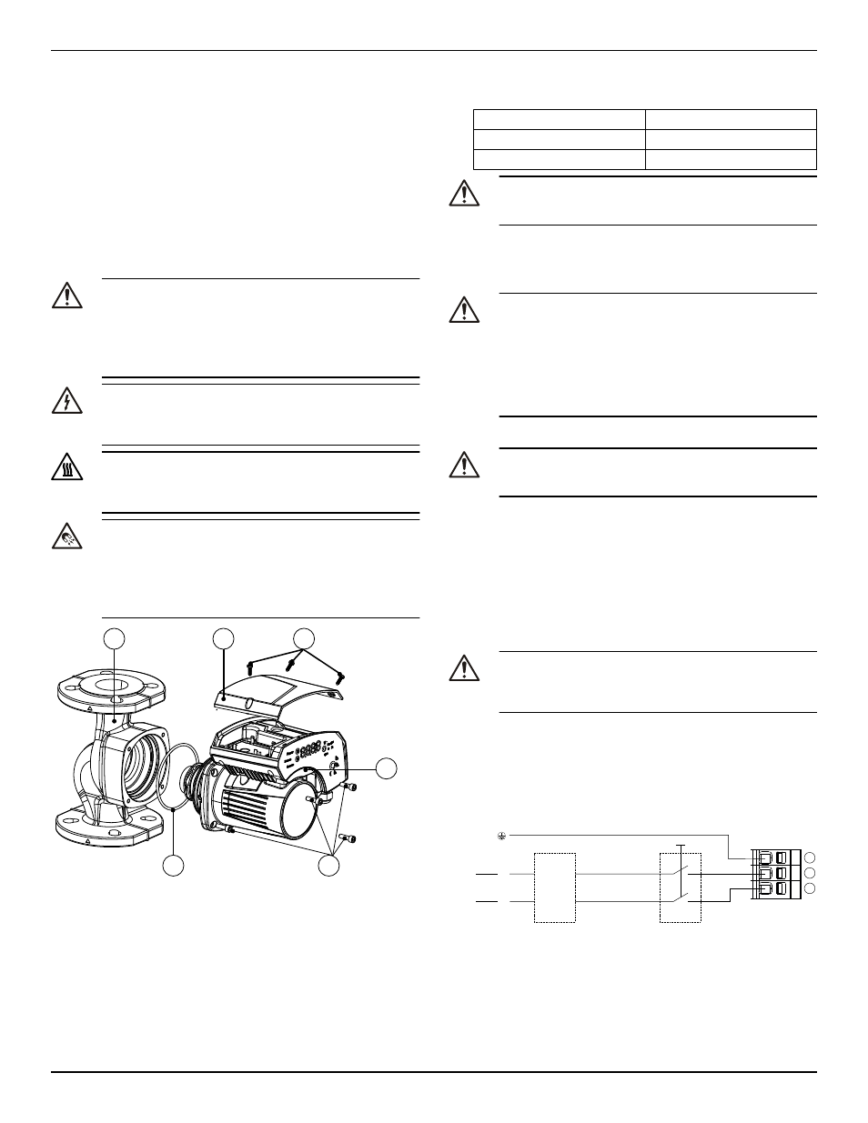
Figure 2: Change the position of the pump head
1.
Loosen the four hex-head screws (2) that fix the motor to the
pump housing (4) using the T-handle allen wrench described.
2.
Rotate the motor (1) in 90° steps to the desired position.
3.
In case of separation of the motor housing from the pump body
(4):
a)
avoid removing the rotating assembly from motor housing;
b)
pay attention to the magnetic hazard listed before.
A defective O-ring must be replaced. An O-ring is already availa-
ble inside the package as spare part.
4.
Properly align and tighten the four hex-head screws (2) that affix
the motor to the pump body (4) according to the torque table giv-
en below in a criss cross pattern.
M6
90 in-lb
M8
170 in-lb
M10
340 in-lb
CAUTION:
Check for the presence of leaks after reassembling the
pump.
4.7 Electrical installation
Precautions
WARNING:
• Make sure that all connections are performed by a quali-
fied electrician in accordance with all applicable codes,
ordinances and good practices. Failure to follow these
instructions could result in serious injury, death and/or
property damage.
• Before starting work on the unit, make sure that the unit
and the control panel are isolated from the power sup-
ply and cannot be energized.
Grounding (earthing)
WARNING:
Reduced risk of electric shock during operation of this pump
requires the provision of acceptable grounding.
Be sure the following are adhered to. Failure to follow these instruc-
tions could result in serious personal injury, death, and/or property
damage.
• If means of connection to the supply connection box (wiring com-
partment) is other than grounded metal conduit, ground the
pump back to service using a copper conductor at least the size of
the circuit conductors supplying the pump.
• Connect the ground wire to the green grounding terminal in the
wiring compartment.
4.7.1 Power supply connection
WARNING:
Do not make any connection in the pump control box unless
the power supply has been switched off for at least 2 mi-
nutes.
For models with standard terminal block connection:
1.
Open the terminal box cover removing the screws (5).
2.
Thread the ½” NPT electrical fitting into the conduit connection of
the pump.
3.
Connect the cable according to the wiring diagram.
a.
Connect the ground wire, if used.
b.
Connect the wires.
4.
Close the terminal box cover.
1
2
3
L
N
115V
L
1
L
2
208-230V
CB
Figure 3: Wiring diagram
4 Installation
ecocirc XL Installation, Operation, and Maintenance manual
7