2 i/o connections, 3 connection assignment, 5 system description – Bell & Gossett P2002548B ecocirc XL High Efficiency Large Wet Rotor Pumps User Manual
Page 10: 1 user interface, 1 user interface locking/unlocking, 2 functions, 1 control mode, 2 i/o connections 4.7.3 connection assignment
Start /
Stop
20
19
18
17
16
15
14
13
12
11
10
9
8
7
6
5
4
3
2
1
C
N
L
NO 15V S+S- P+ P-
T+ T-
A
B
GND
A
B
GND
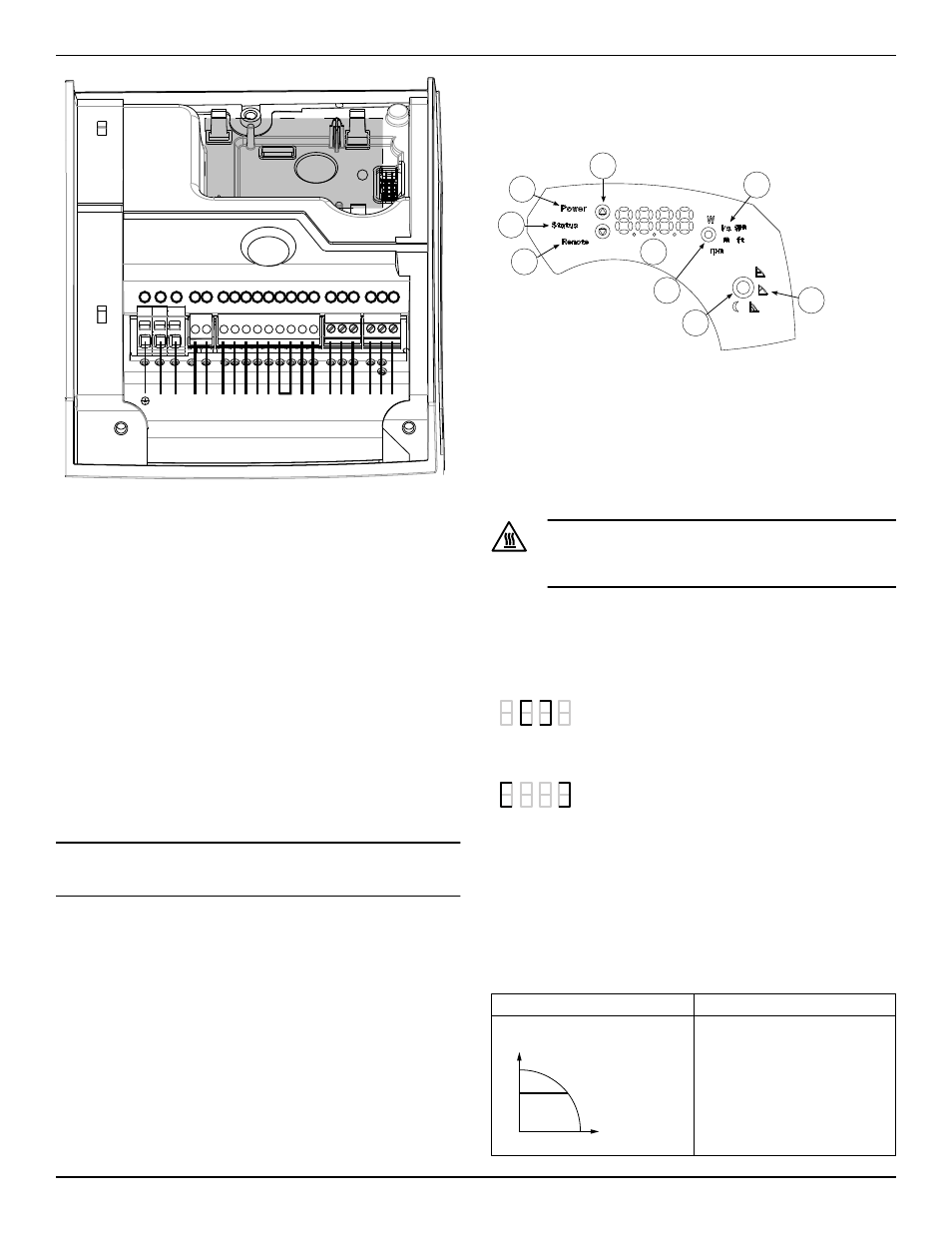
Figure 4: Connection diagram
For cable terminations, see above connection diagram.
4.7.2 I/O connections
1.
Open the terminal box cover removing the screws (5). Refer to fig-
ure 2 on page 7. Use control screwdriver described under section
4.2 to access terminal blocks.
2.
Connect the appropriate wires according to the terminal block di-
agram and the requirements of section
(page 8) given below in section 4.7.3.
3.
Close the terminal box cover.
• For a two-pump connection, wire them through a communication
cable connecting the 2 RS-485 ports at the pumps to terminals 15,
16 & 17.
4.7.3 Connection assignment
• For all electrical connections use heat resistant wires or cable rat-
ed for at least 194°F (90°C). The cables should not touch the mo-
tor housing, the pump or the piping.
• Power and control wires must be run in separate channels.
• Metal conduit for power wiring must only be attached to 1/2” NPT
conduit fitting.
NOTICE:
Cable glands are only available for low voltage wiring to protect
against cable slippage and vapor ingress into the terminal box.
5 System Description
5.1 User interface
9
8
7
6
5
4
2
1
3
Figure 5: User interface diagram
1.
Control mode button
2.
Control mode indicators
3.
Parameter button
4.
Parameter indicators
5.
Setting buttons
6.
Numeric display
7.
Power indicator
8.
Status / Fault indicator
9.
Remote control indicator
Hot Surface:
Burn hazard. During the normal operation, the pump surfa-
ces may be so hot that only the buttons should be touched to
avoid burns.
5.1.1 User interface locking/unlocking
The user interface will automatically lock if no button is pressed for ten
minutes, or if the upper setting button (5) and the parameter button (3)
are pressed for two seconds. See
If a button is pressed when the user interface is locked, the display (6)
shows:
To unlock the user interface, press the upper setting button (5) and the
parameter button (3) for two seconds. The display (6) will show:
Now it is possible to change the pump setting as preferred.
5.2 Functions
The main functions of the pump and control modes are selectable
through the pump user interface and the embedded I/O. Advanced
functions or communication features, can only be set via bus protocol
or the optional Wireless module. See the advanced functions manual at
www.bellgossett.com.
5.2.1 Control mode
Mode
Description
Constant pressure
Hset
The pump maintains a constant
pressure at any flow demand. The
desired head of the pump can be
set via user interface. See section
6.1.2 Change set point.
5 System Description
8
ecocirc XL Installation, Operation, and Maintenance manual