Xylem 702 MJK Comtroller User Manual
Page 8
8
M702GB/0110 Rev. 111001
ComTroller 702
3
Menus
3.1
F0 - Unit type/ID, software version, clock
and protocol type
Menu F0 show the MJK unit type, protocol type,
program version and date / time.
MJK 702 : 3
COMLI 830802
16:07:29
24/10/01
In above example, the Data Transmitter is
connected to a Comtroller 702 with unit ID no. 3.
The Unit ID no. is set binary by means of 8
switches on the front panel. (All OFF = 0 - All ON =
255.) Note! The unit ID no. must be set within the
range 1 to 247.
3.2
F1 - Inputs on/off
In menu F1 is shown whether the digital inputs are
ON or OFF.
INPUTS
1 2 3 4
ON :
OFF:
In above example, DI no. 1 and 2 are ON while DI
3 and 4 are OFF.
A delay time can be set individually for each digital
input in order to allow the input to go ON without
activating i.e. an alarm. (See section 6.)
When the input is OFF an empty field is shown.
When the input is ON, the field will flash for the
duration of the delay time. When the delay time
has expired, a full field will be lit.
3.3
F2 - Outputs on/off
Menu F2 show the status of the digital outputs.
OUTPUTS
1 2 3 4
ON :
OFF:
In above example, DO no. 1 and 2 are ON while
DO 3 and 4 are OFF.
A delay time can be set individually for each digital
output in order to delay the activation of the
corresponding output relay. (See section 7.)
When the output is OFF an empty field is
shown. When the output is ON the field will flash
for the duration of the delay time. When the delay
time has expired, the output relay is activated and
the field will be shown in a steady state .
3.4
F3 - Limits high/low
Menu F3 indicate if the high and low limits for the
analog inputs are exceeded.
The first two fields indicate if the high limits are
exceeded and the last two show if the low limits
are exceeded.
LIMITS HIGH/LOW 1 2
3 4 5 6
1 2
ON : OFF:
A delay time can be set individually for each analog
input allowing the input to exceed the limit
momentarily without i.e. activating an alarm. (See
section 5.)
If the analog input are within limits, the field will be
empty. If the limits are exceeded, the field will flash
during the delay time. When the delay time has
expired, the field is shown in a steady state.
3.5
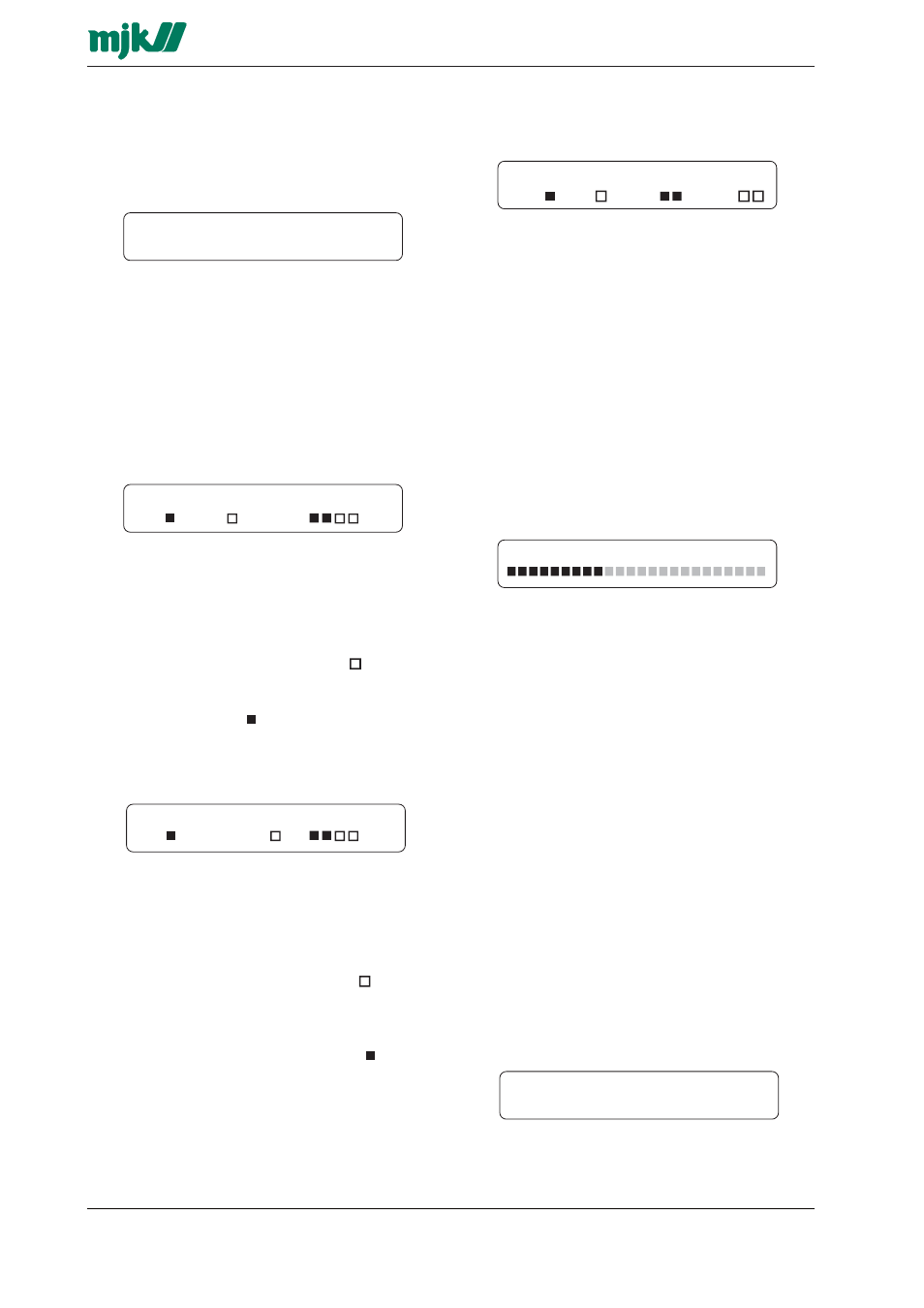
F4 - Analog inputs #
Menu F4 shows the immediate value of an analog in-
put as a horizontal bar formed of up to 24 fields. If the
input signal is 4 (0) mA (see also section 5.2), none of
the fields is lit (0 %). If the input signal is 20 mA, all 24
fields is lit (100 %).
ANALOG INPUT NO #
Select the desired analog input with the arrow
keys or by keying the corresponding input number
(1 - 2).
3.6
F5 - Analog input scaled
Menu F5 shows the immediate value of an analog
input in digits rather than a horizontal bar as in the
previous menu.
The first set of digits read out the signal value as
the percentage between the low mA value (0/4
mA) (see also section 5.2) and the high mA value
(20 mA). The next set of digits read out the same
signal multiplied with a programmable scaling factor.
The readout scaling is determined by programming
the desired readout range corresponding to the
low mA value (0 / 4 mA) and the high mA value (20
mA) respectively. If e.g. a tank level is measured,
and the level varies between 2 metres and 3
metres, the low mA value is set to correspond to
"200" and the high mA value is set to "300". A level
measurement of i.e. 2,5 metres will corespond to a
signal value of 50 %, resulting in a readout of "250"
(See section 5.3 - 5.4)
ANALOG INPUT NO #
50 % SKALERET 250
Select the desired analog input with the arrow
keys or by keying the corresponding input number
(1 - 2).