Xylem 702 MJK Comtroller User Manual
Page 18
18
M702GB/0110 Rev. 111001
ComTroller 702
15
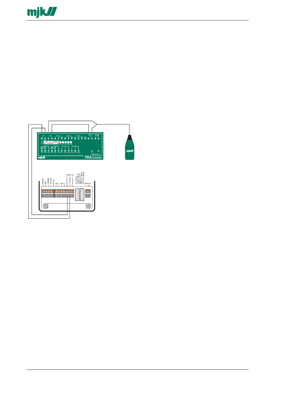
Electrical connection
Al connections are shown on the front panel.
15.1 Digital inputs
The digital inputs (DI 1-4) has optocouplers with
10 k
Ω serial resistors. The inputs can be
configured individually to normally open (NO) or
normally closed (NC).
15.2 Analog inputs
The input can be configured for either 0 - 20 mA or 4
- 20 mA. Below is shown a connection example with
an active a non-active signal source. The pressure
transmitter is an non-active signal source. The active
power source is fed from a separate power supply.
15.3
Serial ports
The Comtroller 702 is equipped with 1 x RS232-
port on terminal 28 - 32, that can be used for
communication to i.e. a PC or PLC that supports
the current communications protocol.
2 RS485 ports is available on terminal 23 - 25 and 26
- 28 for communication via owned lines / APL-lines.
Comtroller 702 is equipped with a repeater, so
maximum distance between every Comtroller on the
multidrop line can be obtained.
15.4
External 15 V DC supply
Terminal 33 / 34 is a 15 V DC output for external
use. Max. load 100 mA.
15.5
Software upgrade
If a software upgrade becomes necessary, it is
possible to perform the upgrade yourself. The soft-
ware is loaded into an EPROM. Do the following to
change the EEPROM::
Select NO in the menu "Alarm - call by telephone"
is selected (see section 6.5)
Disconnect the Comtroller 702.
Remove the old EPROM from the socket and
insert the new one. Note that the little notch in the
EEPROM is oriented correctly in relation to the
socket.
Connect the Comtroller 702.
Remember to select "Alarm - call by telephone".