Basic settings, Display and keyboard – MJK Automation Shuttle Ultrasonic Level Transmitter and Sensor User Manual
Page 16
16
GB Shuttle Manual 100316
SW 838023
Display and keyboard
Basic settings
The automatic setting of the zero point and the mA output made by Shuttle
®
during initial
startup may be adequate.
If changes of the zero point read-out and mA output setting should be necessary, and when
Shuttle
®
is to be used as a pump controller or for level monitoring, an additional 5 settings
should be made. These settings are described in detail on the following pages.
Proceed with set-up in the order listed below:
1: Setting units of measurement
See page
17
.
2: Setting the distance from sensor to zero point and
Setting the level read-out:
See pages
18
-
19
.
3: Setting the mA output:
See page
20
.
4: Setting the the relay limits:
See page
21
.
5: Start of the learning function:
See pages
28
-
29
.
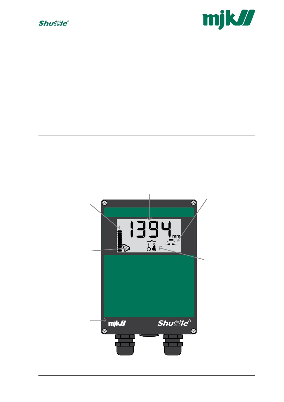
Bar graph
The bar graph can
be set to indicate
either the level
read-out or the mA
output.
Alarm
A flashing bell
indicates, that a
level is exceeded
or that Shuttle
®
is
not certain that the
measured level is
correct.
Display
Shuttle
®
continuosly reads
out the current level with
bright and easy-to-read
figures.
Echo strength
Shuttle
®
indicates
that the ultrasonic
echo is sufficient
for a reliable level
measurement.
Relay outputs
When Shuttle
®
measures a level
that has exceeded
a setpoint limit, the
relays are activated
and their current po-
sition are indicated
here. (Relay no. 2 is
activated.)
MJK
will always be at
your disposal.
When the settings are made, Shuttle
®
is ready to be put into service.