Display and keyboard – MJK Automation Shuttle Ultrasonic Level Transmitter and Sensor User Manual
Page 12
12
GB Shuttle Manual 100316
SW 838023
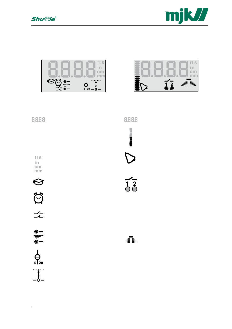
Display and keyboard
Displayed during normal service
Numerical read-out of the actual
level.
Bar graph for indication of the signal
level on the mA-output or for indica-
tion of the actual level.
Alarm symbol. The symbol is shown
if a system error should occur on the
Shuttle
®
.
See also pages
24
and
27
.
Indication of the status of the output
relays and whether the output relays
are in use. The round dot below
the relay number will appear steady
when the relay is activated and will
appear flashing when the relay is
about to be activated after a preset
time delay.
See also pages
22
-
24
,
26
and
27
.
This group of symbols indicates the
strength of the received ultrasonic
echo. A good measuring signal is
indicated by three or more sets of
archs.
See also page
32
.
Displayed during programming
Numerical read-out of limit values.
delays and other numerical settings
and selections. Is also used to show
an initial letter code at start up of the
special settings.
See also pages
46
-
69
.
Displayed when selecting the de-
sired measuring unit (see page
17
)
and when selecting time delays.
Start / activation of the learning
function. See also pages
28
-
29
.
Flashes when setting the time
delays.
See also pages
22
-
24
,
26
and
27
.
Displayed when programming the
output relays.
See also pages
23
-
24
,
26
and
27
.
Displayed when setting the start and
stop levels for the output relays.
See also pages
21
-
23
and
25
-
26
.
Displayed when setting the zero
point and span for the mA output.
See also page
20
.
Displayed when setting the distance
between sensor and zero point and
setting of level read-out.
See also pages
18
-
19
.
The segments shown will be lit during
programming of the Shuttle
®
.
The segments shown will be lit when
Shuttle
®
are in normal service.
The display symbols
The different display segments indicates the actual level, the state of the output relays etc.
during normal service and indicates limit values, selection of measuring unit and other set-
tings during programming.