Troubleshooting pneumatic, Electrical, Maintenance – Bell & Gossett HS 618B Series GT610-IP Electronic-Pneumatic Transducer User Manual
Page 4
Xylem Inc.
8200 N. Austin Avenue
Morton Grove, Illinois 60053
Phone: (847) 966-3700
Fax: (847) 965-8379
www.xyleminc.com/brands/bellgossett
Bell & Gossett is a trademark of Xylem Inc. or one of its subsidiaries.
© 2012 Xylem Inc. HS-618B October 2012 Part No. 511134
TROUBLESHOOTING
Pneumatic
1. Check supply pressure. It should be constant 35 psig
(241 kPa) for the 6-30 psig (41-207 kPa) units. 100
psig (690 kPa) is maximum useable supply pressure.
2. Make certain that pressure connections are tight.
3. Check start point and span as previously outlined.
4. Check to see if wire screen is obstructed.
5. Check diaphragms (10) and (11) for rupture and
replace if necessary. See disassembly procedure
under "Maintenance".
6. If disassembly of transducer is necessary, it is recom-
mended it be done in a clean area. Should foreign par-
ticles enter any area of the assembly a malfunction
may occur. Do not attempt to remove magnet housing
subassembly as this will destroy the calibration of the
nozzle and flexure assembly relationship.
7. If the maximum specified output pressure cannot be
obtained, verify the supply pressure using an alternate
gauge. Also, verify the input using a digital multimeter.
Some field calibrators may not be capable of supplying
sufficient current to the higher voltage units.
Electrical
1. Is it proper 4-20 mA DC or 1-9 VDC range?
2. Check to see that input signals leads are connected to
proper terminals. (Refer to Electrical Connection section).
3. Make certain there are no loose wires at terminal
connections.
4. Check internal resistance by connecting ohmmeter to
terminal block. In making any resistance tests, the input
signal wires from controller must be disconnected.
Do not change setting of range adjust potentiometer
on printed circuit board while making this test.
Input Range
Nominal Input Impedance
4-20 mA DC
225 ohms
1-9 VDC
535 ohms
MAINTENANCE
Under normal conditions, no maintenance should be
required. If disassembly is necessary, refer to "Pneumatic
Troubleshooting" section. It is important that clean, dry air
be supplied to the unit at all times.
Periodically inspect the diaphragm (11) and diaphragm
assembly (10) to see if the diaphragms show any signs of
wear. To inspect the diaphragms, remove the four 10-32
fillister head screws. Then remove the pilot body sub-
assembly (6) and spacer (5). To check for any foreign
matter which may have accumulated around the nozzle
plug, remove cap nut (7), O-ring (8) and plug spring (9).
Exercise caution when inspecting the nozzle plug to avoid
damaging the seating surface on the plug or in the pilot
body. When reassembling the booster relay be sure to
properly orient the bleed hole.
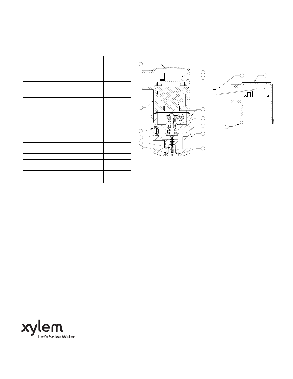
13
2
1
13
14
3
3
5
6
7
4
12
11
10
9
8
Item
Description
Qty.
No.
Required
1
Printed Circuit Board
1
4-20/10-50 MA DC
0-5/1-9 VDC
1
2
PC Board Support Post
4
3
Cover Mounting Screws
4
PHMS #6-32 x 1/4" long
4
Bias Spring
1
5
Spacer (exhaust)
1
6
Pilot Body Subassembly
1
7
Cap Nut
1
8 (1)
Cap Nut O-ring
1
9 (1)
Pilot Spring
1
10 (1)
Diaphragm Assembly
1
11 (1)
Upper Diaphragm
1
12
Cover
1
13
Cover Grommet
1
14
Lead Wire (18" (457mm)
1
Long - 18 GA) Pos.-Red
Negative - Black
1
15
Mounting Bracket
1
(not shown)
WARNING: Manufactured with (1, 1, 1-Trichloroethane),
a substance which harms public health and
environment by destroying ozone in the upper
atmosphere.