Installation – Bell & Gossett HS 232C Series I In-line Float and Thermostatic Steam Traps User Manual
Page 3
3
INSTALLATION –
Series I In-line Float and Thermostatic Steam Traps
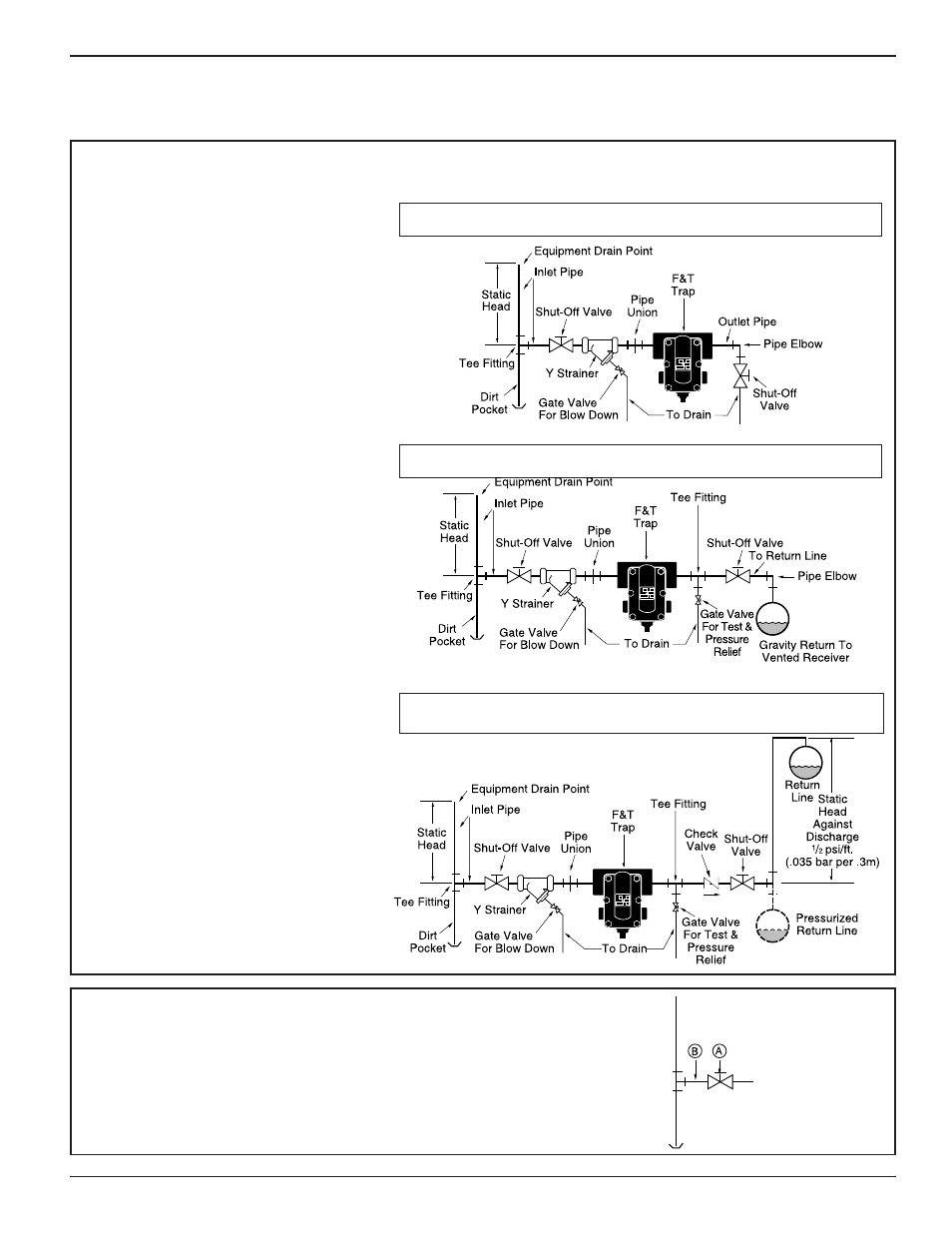
TYPICAL PIPING DIAGRAMS
Trap Draining to Open Drain
Trap Draining to Gravity Return Line
Trap Draining to Overhead Return Line
or Pressurized Return Line
1. Determine where to install the trap,
based on the following requirements:
a. The trap must be located as close
as possible and below the equipment
to be drained.
b. The trap must be in a straight run
of horizontal pipe and pitched to
allow condensate to flow into the
trap inlet and away from the
trap outlet. Refer to the Typical
Piping Diagrams at the right.
c. Plenty of space around the trap is
needed for servicing, which may
include removal of the body or cover.
2. Install a shut-off valve (A) on the inlet pipe (B).