Putting the unit into ser vice, Selector or v acuum switch settings – Bell & Gossett DN0153D HS Vacuum Heating Units Series HV User Manual
Page 4
4
Install gate valve in return line for testing pump shut off vacu-
um, closing off hot returns when cleaning strainer, etc. Do not
install check valve in return line. Avoid elbow or tee located
closer to strainer inlet than 10 times inlet diameter. If unavoid-
able relocate vacuum switches to top of nearest “dry” point on
return main unless a portion of return is below pump inlet an
accumulation tank is recommended. Accumulator tank may
not be necessary if low length of return is not lower than 24"
below pump inlet or longer than 30'. See TYPICAL PIPING-
LOW RETURNS. High pressure steam traps should empty into
uninsulated flash tank where condensate will cool before
entering unit.
DISCHARGE LINE
Install union, check valve, steam cock and gate valve at unit in
each discharge line. Steam cock to be adjusted to cause
pump to operate at specified pressure. If discharge line is
more than 100' long, install pipe 1 or 2 times larger than dis-
charge valve tapping.
ELECTRICAL WIRING &
CONTROLS
Connect power wiring per NEC. Recheck nameplate vs. speci
-
fications and conditions. All single phase motors have internal
thermal protection.
Three phase motors must use starters with properly sized
overload relays. Overload relays furnished are designed for
manual reset.
WARNING:
HIGH VOLTAGE ELECTRICITY
Disconnect and lock out power before connecting or
servicing unit. Failure to follow these instructions could
result in serious injury or death.
POSITION
WHEN USED
OPERATION
“Vacuum and Float” or “Fl-Vac”
Normal position
Pumps operate on either low
vacuum or high condensate
“Float Only” or “Float”
Sometimes used for night and week-end service. This
Pump starts and stops on
setting not recommended for use with lift fitting.
Condensate level change
“Continuous” or “Hand”
Testing and for unusually high
Continuous
lift conditions in return lines.
“Off” (Duplex Units only)
Adjust controls, inspect pump
Prevent operation of motor
PUTTING THE UNIT INTO SER
VICE
1.
Assure that the unit is piped in accordance with instructions.
2. Isolate tank before performing any system leak test. Do
not pressurize the tank as part of the leak test. Failure to
do this can result in serious injury or death.
3. Check floats for free operation.
4. Check power leads in accordance with wiring diagram
enclosed in control cabinet (when furnished).
5. Install drain plugs.
6. Fill receiver (upper compartment on Series HV) half full of
water to prime pump(s) and prevent possible damage to
pump seals. Avoid freezing conditions after unit receiver
has been filled.
7. Check for proper rotation of all three phase motors.
Rotation must be clockwise looking down on the motor as
indicated by directional arrow on pump casting. If pump
runs backwards, interchange two wires (3 phase only).
8. Throttle plug cock in discharge line until pressure at pump
(while pump is discharging) approaches pump rated pres-
sure. Tighten plug nut to secure adjustment.
9. Remove start-up label (below) from panel (if applicable)
after complying with instructions.
10. If possible, observe operation thru several cycles using
selector or vacuum switch settings as noted below.
SELECTOR OR V
ACUUM SWITCH SETTINGS
The vacuum switches are adjusted and tested at the factory
for proper operation. The vacuum switch on a single unit and
the lead switch of a duplex unit is set to close at 3" Hg vacu-
um and open at 8". The lag switch of a duplex unit is set to
close at 2" and open at 8".
These settings are suitable for all normal installations including
those having an accumulator tank or lift fitting. If settings must
be readjusted refer to manufacturer’s instructions.
WARNING:
HIGH VOLTAGE
Disconnect and lock out power before connecting or
servicing unit. Failure to follow these instructions could
result in serious injury or death.
CAUTION:
DO NOT RUN DRY.
SEAL DAMAGE MAY OCCUR.
Inspect pump seal regularly for leaks. Replace as required.
Failure to follow these instructions could result in injury or
property damage.
CAUTION:
DO NOT REVERSE
Reverse operation can cause extensive damage to
pumps. Jog the motor to test for direction of rotation.
Failure to follow these instructions could result in injury or
property damage.
ELECTRICIAN/INSTALLER/OPERATOR
REMOVE AND DESTROY THIS TAG AFTER —
1. ASSURING THAT ALL PUMPS ROTATE CLOCKWISE PER ARROWS
CAST ON VOLUTES. (JOG PUMP MOMENTARILY TO TEST – INTER-
CHANGE ANY TWO MOTOR POWER WIRES TO REVERSE 3PH
MOTORS.)
2. ASSURING THAT SHIPPING LOCKS HAVE BEEN REMOVED FROM ALL
FLOAT SWITCHES.
WARNING:
EXPLOSIBLE
Do not pressurize receiver. Isolate receiver during
leak test. Do not plug overflow. Do not restrict vent opening
to atmosphere. Open valves slowly. Failure to follow these
instructions could result in serious injury or death.
3
Receivers are non-code cast iron.
PRELIMINARY INSPECTION
Assure that there is no shipping damage.
Assure that nameplate ratings agree with job specifications
and actual conditions.
HANDLING
Use care in installing unit.
LOCATION
Place unit for easy access to all parts. Allow adequate space
for servicing. Check ambient conditions.
NOTICE / TEMPERATURE LIMITS
Motors are designed to operate in 104
°F max. ambient.
Insulate or ventilate as required.
PIPING (GENERAL)
Pipe the unit per the Elementary Piping Diagram. Locate and
support piping so as to not load the discharge valve.
PIPING
(Vent)
Install a vent pipe to atmosphere. Pipe to be size of vent port
on unit. Do not restrict or reduce vent opening or exceed 20
feet vertical height unless an overflow connection is provided.
PRIMING PORT
Provide a priming port as shown on piping diagram.
FLOAT SWITCHES
Floats are locked in place to prevent damage during shipment.
Remove shipping locks. Check factory settings. Floats are
adjustable for various levels of operation.
See page 7 for detailed instructions.
EQUALIZING LINE
An equalizing line must be installed with all Series HV units.
This line must be installed to prevent formation of a vacuum
on the radiation side of the system when steam stops flowing
in the mains. This vacuum may be higher than return line vac-
uum, which would prevent condensate from flowing back to
the pump. To correct this in an unzoned system, install equal-
izer line as shown in the piping diagram. To correct this in a
zoned system, install equalizer line for each zoned section or
install a vacuum breaker on supply line on radiation side of
each zone control valve.
PIPING
(Returns)
Gravity return lines from system must be properly pitched
down to unit inlet. Returns must also be trapped to prevent
steam entry into the unit. An inlet basket strainer is
recommended.
CAUTION:
UNIT LIFTING EYE
Use unit lifting eyes only to lift unit as shipped from
factory. Unit must be empty and disconnected from pipes,
anchors and other restraints. Use proper rigging pro-
cedures. Failure to follow these instructions could result in
injury or property damage.
CAUTION:
NOT A CHEMICAL PUMP
Inject boiler feed compounds from chemical feed
tank into boiler feed piping – never into condensate tank.
Failure to follow these instructions could result in injury or
property damage.
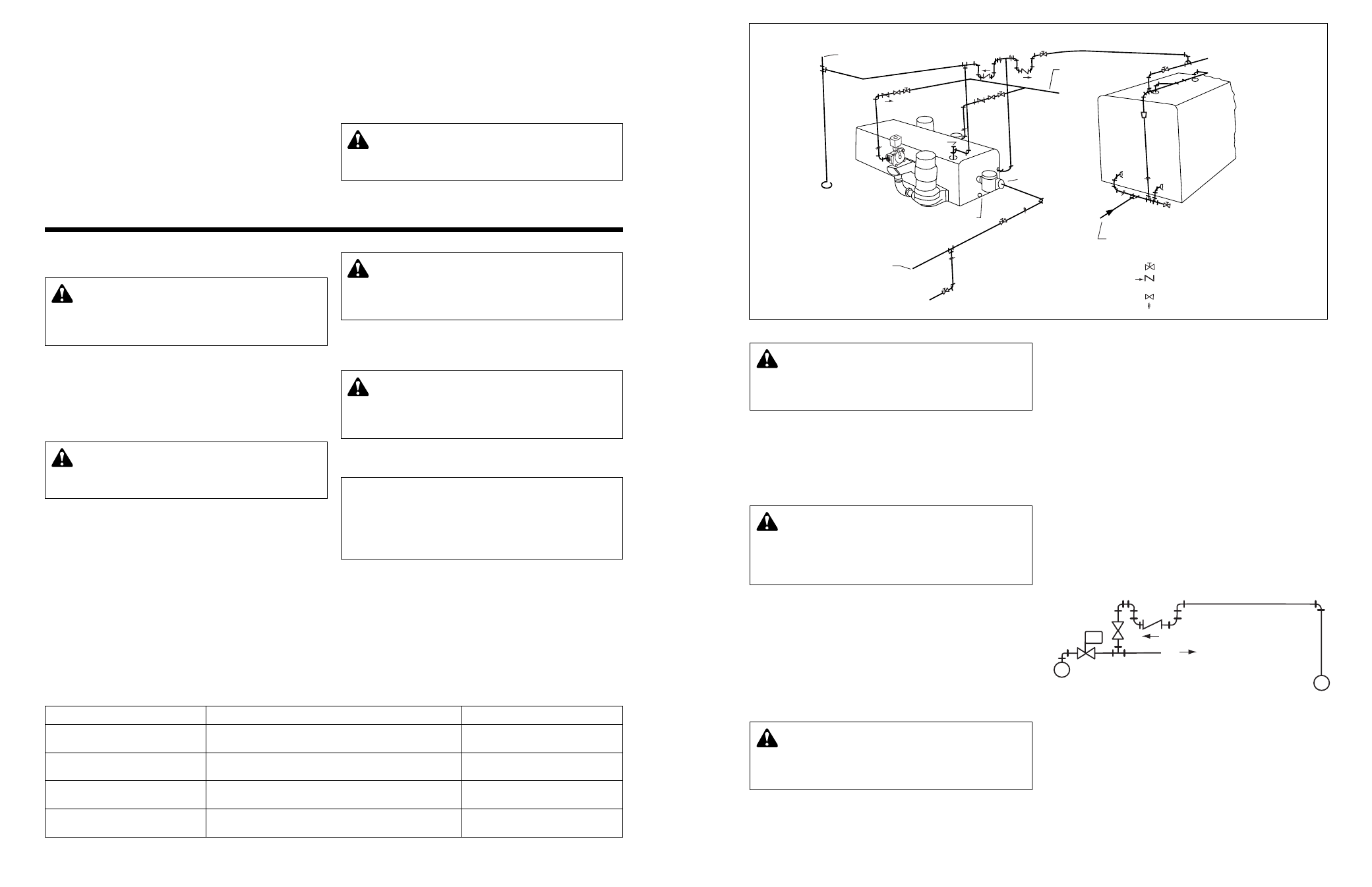
TO BOILER
FEED
SYSTEM
REDUCER
STRAINER
SERIES VLR DUPLEX
PIPING DIAGRAM
DRAIN
DRAIN
DRAIN
DV
PRIMING
OPENING
EQUALIZING LINE —
3
/
4
"
BOILER
FROM BOILER
FEED SYSTEM
— GATE VALVE
— DISCHARGE VALVE
DV
— STEAM OR PLUG COCK
— UNION
— CHECK VALVE
OPEN VENT ABOVE
BOILER WATER LINE
RETURN FROM
HEATING SYSTEM
EQUALIZING CONNECTIONS FOR ZONED SYSTEMS
ZONE CONTROL
VALVE
STEAM MAIN
M
TO ZONE
RETURN MAIN
FIG. 4
FIG. 3
WARNING: EXPLOSIBLE
Do not pressurize receiver. Isolate receiver during
leak test. Do not plug overflow. Do not restrict vent opening
to atmosphere. Open valves slowly. Failure to follow these
instructions could result in serious injury or death.