Bell & Gossett DN0153D HS Vacuum Heating Units Series HV User Manual
Warning, Hoffman specialty, Vacuum heating units series hv
INSTRUCTION MANUAL
DN0153
REVISION D
Hoffman Specialty
®
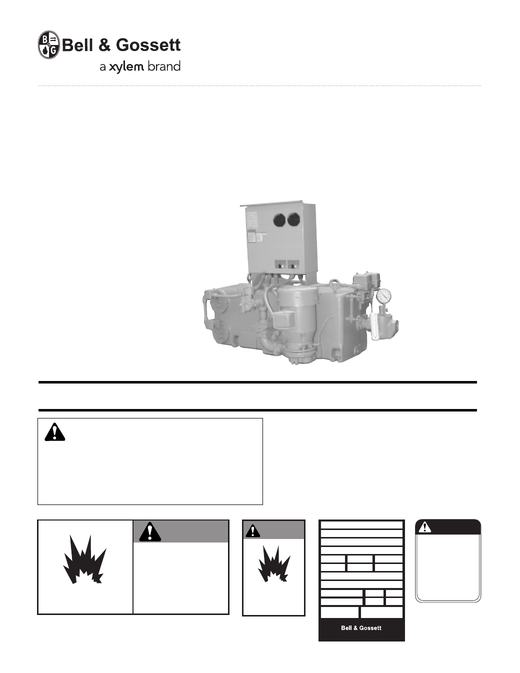
Vacuum Heating Units
Series HV
™
(1,000-20,000 Sq. Ft. EDR)
SERIES HV
UNITS
25,000-60,000 SQ. FT/. EDR
Morton Grove, Illinois 60053
TM
SERIES HV
MODEL
SERIAL
GPM
PSI
PUMP
CFM
IN HG.
PUMP
DWGS
POWER V.
PH.
HZ 60
CONTROL V.
PH. 1
HZ 60
TOTAL
LARGEST MOTOR
F.L. AMP
F.L. AMP
DN0016
HOFFMAN SPECIALTY
®
INST
ALLER:
PLEASE LEA
VE THIS MANUAL FOR THE OWNER’S USE.
SAFETY
INSTRUCTIONS
This safety alert symbol will be used in this manual and on
the unit safety instruction decals to draw attention to safety
related instructions. When used, the safety alert symbol
means ATTENTION! BECOME ALERT! YOUR SAFETY IS
INVOLVED! FAILURE TO FOLLOW THESE INSTRUCTIONS
MAY RESULT IN A SAFETY HAZARD.
CAUTION
DO NOT RUN PUMP DRY,
SEAL DAMAGE MAY OCCUR.
INSPECT PUMP SEAL
REGULARLY FOR LEAKS,
REPLACE AS REQUIRED.
FOR LUBRICATION
REQUIREMENTS, CONSULT
SERVICE INSTRUCTIONS.
FAILURE TO FOLLOW
INSTRUCTIONS COULD
RESULT IN INJURY OR
PROPERTY DAMAGE.
P70644
EXPLOSIBLE
WARNING
DO NOT PRESSURIZE TANK.
ISOLATE TANK DURING LEAK TEST.
DO NOT RESTRICT VENT.
DO NOT PLUG OVERFLOW.
OPEN INLET VALVES SLOWLY.
DO NOT USE AS A FLASH TANK.
FAILURE TO FOLLOW
INSTRUCTIONS COULD RESULT
IN SERIOUS INJURY OR DEATH.
(2) All Units
DN0483 (Small) - DN0484 (Large)
DN0116 Units with Panel
P70644 All Units
EXPLOSIBLE
WARNING
ISOLATE TANK
DURING LEAK TEST
(2) All Units
DN0485 (Small)
DN0486 (Large)
If the decals as noted below are missing or are illegible con
-
tact your local B&G representative for a replacement.
1. Electrical connections to be made by qualified Electrician in
accordance with all National, State and Local codes.
2. Motor must have properly sized starter with properly sized
heaters to provide overload and undervoltage protection.
3. If pump, motor or piping are operating at extremely high or
low temperatures, guarding or insulation is required.
4. Operating personnel should be trained in the operation of
pumps and associated systems (condensate, boiler feed, etc.).
2
DESCRIPTION AND INST
ALLATION
The Series HV vacuum heating units are designed to serve the
dual purpose of pumping accumulated condensate back to
the boiler feed tank and maintaining vacuum in the conden-
sate system. This vacuum will draw air out of the system
on start-up and facilitate the flow of steam thru the heating
system.
One pump/vacuum producer/discharge valve assembly con-
trols both the condensate discharge and the production of
vacuum. Two pump (duplex) units have a second assembly for
backup and to provide extra capacity to handle peak loads.
Various electrical controls are offered to meet system require-
ments. These controls are normally supplied as part of the
assembled unit and a wiring diagram is furnished with the unit.
Refer to this electrical diagram as required.
The units respond to both changing condensate levels and
system vacuum requirements. The Series HV units feature a
low inlet height and therefore have a second float (in the lower
compartment). As condensate accumulates in the lower com-
partment, this float starts the pump and siphons the conden-
sate to the upper chamber.
In operation the centrifugal pump circulates condensate from
the upper compartment thru the multi-jet nozzle creating mul-
tiple jets of water entering the venturi. These jets entrain air
and gasses creating a smooth steady vacuum in the lift mani-
fold and in the condensate system. The air and gasses are
separated in the upper compartment and vented to atmos-
phere. See Figure 1.
Low system vacuum or high water in the upper compartment
or high water in the lower compartment will start the pump to
create vacuum and transfer water to the upper tank. High
water level in the upper compartment will also cause the dis-
charge valve to open.
When the vacuum and float switches have been satisfied and
the pump stops, the check valve in the lift manifold closes,
preventing the return of air and water to the system.
The solenoid operated discharge valve is opened in response
to the condensate level float switch in the upper compartment.
Controlled opening of the discharge valve holds sufficient
back pressure in the nozzle body that the vacuum producer
continues to function even when discharging condensate
(simultaneous rating).
NOZZLE BODY
MULTI-JET NOZZLE
VENTURI
PUMP SUCTION
SOLENOID OPERATED
DISCHARGE VALVE
DISCHARGE
LIFT MANIFOLD
CHECK VALVE
CENTRIFUGAL PUMP
LOWER COMPARTMENT FLOAT SWITCH
UPPER COMPARTMENT FLOAT SWITCH
STRAINER
LOW INLET
VACUUM GAUGE
VACUUM BREAKER
VACUUM SWITCH
AIR VENT
FIG. 1 CUT-AWAY VIEW OF SINGLE SERIES HV SINGLE UNIT: TYPICAL OF ALL SINGLE AND DUPLEX MODELS
AIR VENT
RECEIVER
INLET
MULTI-JET NOZZLES
VENTURI
NOZZLE
BODY
CENTRIFUGAL PUMP
DSK-1328
SOLENOID
DISCHARGE
VALVE
FIG. 2
SERIES HV VACUUM PRODUCER
SERIES HV
UNITS
1,000 – 20,000 SQ. FT/. EDR