Hurling chamber floa t switch adjustment, Control p anel selector switch settings – Bell & Gossett DN0136C Domestic Pump Vacuum Heating Units Series VCL User Manual
Page 8
8
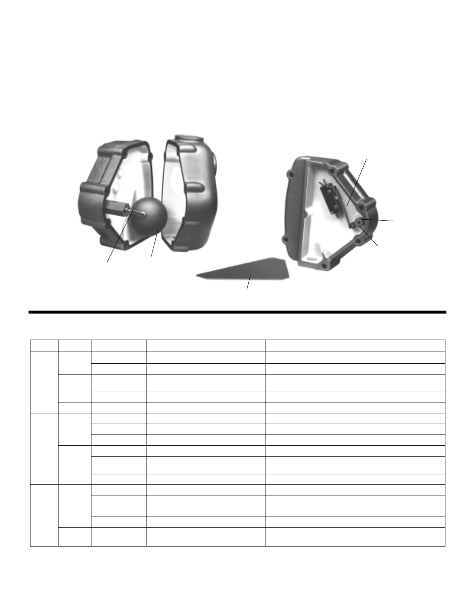
The switch which controls the hurling water makeup valve is
located inside the float housing near the vacuum unit overflow.
The switch is under a triangular coverplate which is retained by
one #6 screw (loosen bolts retaining the cover edges only if
necessary). The actuating cam can be rotated for testing by
using a screwdriver in the slot provided.
Adjust the switch location so that the switch snaps at approx-
imately mid-range of the cam travel. The #6 screw near the
cam goes thru a slot in the switch mounting plate. Loosen this
screw (and farthermost screw thru the switch) to permit adjust-
ment of the switching position. Tighten screws and recheck
operation after making any adjustment.
The cam should be positioned on the shaft for maximum
switch roller movement in operation. The cam is retained by a
socket set screw.
Replacement seal tube assemblies are available in case of
leakage around the float pivot shaft.
HURLING CHAMBER FLOA
T SWITCH ADJUSTMENT
Pump
Model
Position
Purpose
Operation
VCD 2
Automatic
Normal.
Pump starts on high condensate level, stops on low.
Off
Adjust controls, inspect pump.
Prevent operation of motor. Caution: See footnote 1.
VCD 3
Lead
Set one switch to “lead”, other to “lag”.
Lead pump starts first on high condensate level, lag pump
and
Lag
Reverse periodically.
runs in emergency.
VCD4
Off
Adjust controls, inspect pump.
Prevent operation of motor. Caution: See footnote 1.
Any
Hand
Test rotation and/or pressure.
Caution – Pump may run dry and damage seal.
VCD 2
Automatic
Normal.
Pump starts on low vacuum, stops on high vacuum.
and
Off
Sometimes right or week-end.
2
Unit operates as a simple condensation pump.
VCD 3
Continuous
Testing or high lifts in returns.
Pump operates continuously.
Off
Sometimes right or week-end.
2
Unit operates as a condensation pump.
Lead
Set one switch to “lead”, other to “lag”.
Lead pump starts first on low vacuum, lag pump also runs on
VCD 4
Lag
Reverse periodically.
start up or with large system leaks.
Continuous
Testing or high lifts in returns.
Air pump runs continuously.
VCD 2
Float & Vacuum
Normal.
Pump starts on high condensate level or low vacuum.
4
Float Only
Sometimes night or week-end.
2
Air pump responds only to condensate level change.
VCD 3
Continuous
Testing or high lifts in returns.
Pump operates continuously.
VCD4
Off
Adjust controls, inspect pump.
Prevent operation of motor. Caution: See footnote 1.
VCD 4
No. 1 pump leads
Set one switch to “lead”, other to “lag”.
Lead pump starts first on float and/or vacuum depending on
Only
No. 2 pump leads
Reverse periodically.
setting of other vacuum pump selector switch.
CONTROL P
ANEL SELECTOR SWITCH SETTINGS
W
A
TER
AIR
AIR WITH
ACCUMULA
TOR
3
1
Caution – this is not a disconnect switch for power supply.
2
Not recommended for systems with lift fittings.
3
Air pumps respond to conditions in accumulator tank.
4
Duplex air pump runs on abnormally high rate of condensate flow, and on start-up.
FLOAT ROD
MICRO SWITCH
CAM
FLOAT BALL
CAM SET
SCREW
INSPECTION PLATE