Description, Representative piping diagram – Bell & Gossett DN0136C Domestic Pump Vacuum Heating Units Series VCL User Manual
Page 2
2
DESCRIPTION
The Series VCD and Series VCL vacuum heating units ar
e
designed to serve the dual purpose of pumping accumulated
condensate back to the boiler feed tank and maintaining
vacuum in the condensate system.
These units have separate compartments for the vacuum pro-
ducer (the hurling water chamber) and for the condensate (the
condensate receiver).
The 25VCD and 50VCD models have both compartments inte-
grally cast in one casting while the 100 and 150 VCD models
have separate compartments bolted together with external lift
pipes connecting them.
Series VCL units are customized to user specifications and
constructed using a choice of rectangular cast iron condensate
receivers, underground receivers, or cylindrical steel receivers.
In the case of steel condensate receivers, the vacuum unit can
be mounted on this receiver or mounted separately and field
piped. All models will have one or two condensate pumps and
one or two vacuum pumps as specified.
A variety of control options are available and furnished as spec-
ified. When control panels are factory supplied, electrical dia-
grams are shipped in the cabinets.
Receivers and hurling chambers are non-code cast iron or
steel.
PRELIMINAR
Y INSPECTION
Assur
e that there is no shipping damage.
Assure that nameplate ratings agree with job specifications and
actual conditions.
HANDLING
Use car
e in installing unit. Utilize Lifting Eyes equally when
slinging.
LOCA
TION
Place unit for easy access to all parts. Allow adequate space
for servicing. Check ambient conditions.
NOTICE/TEMPERA
TURE LIMITS
Motors ar
e designed to operate in 104°F (40°C) max. ambient.
Insulate or ventilate as required.
PIPING
(General)
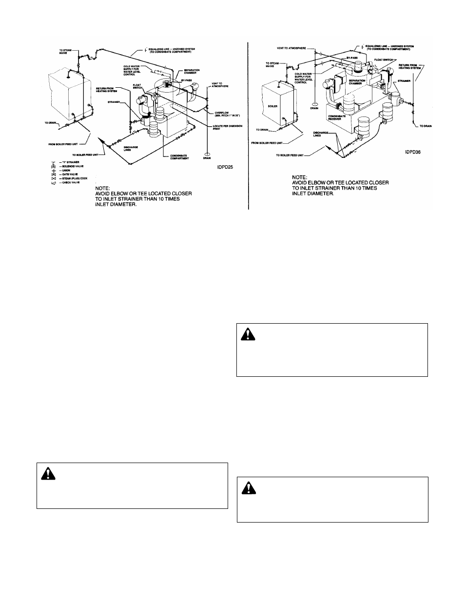
Pipe the unit per the Repr
esentative Piping Diagram. Locate
and support piping so as to not load the pump discharge.
W
ARNING: EXPLOSIBLE
Do not pr
essurize receiver. Isolate receiver during leak
test. Do not plug overflow. Do not restrict vent opening to
atmosphere. Open valves slowly. Failure to follow these
instructions could result in serious injury or death.
CAUTION:
UNIT LIFTING EYE
Use unit lifting eyes only to lift unit as shipped fr
om
factory. Unit must be empty and disconnected from pipes,
anchors and other restraints. Use proper rigging pro-
cedures. Failure to follow these instructions could result in
injury or property damage.
CAUTION:
NOT A CHEMICAL PUMP
Inject boiler feed compounds fr
om chemical feed tank
into boiler feed piping – never into condensate tank. Failure
to follow these instructions could result in injury or property
damage.
FIG. 1
100 & 150 VCD CONFIGURATION
SERIES VCL (NOT SHOWN) USES SIMILAR PIPING
25 & 50 VCD CONFIGURATION
REPRESENTATIVE PIPING DIAGRAM