Bell & Gossett DN0136C Domestic Pump Vacuum Heating Units Series VCL User Manual
Page 3
PIPING
(Returns)
Gravity r
eturn lines from system must be properly pitched down
to unit inlet. Returns must also be trapped to prevent steam
entry into the unit. An inlet basket strainer is recommended.
SUCTION PIPING
Suction piping between the condensate r
eceiver and the
vacuum producer should be at least as large as the inlet to the
vacuum producer.
PIPING
(Vent)
Install a vent pipe to atmospher
e. Pipe to be size of vent port
on unit. Do not restrict or reduce vent opening or exceed 20
feet vertical height unless an overflow connection is provided.
PIPING
(Overflow)
Pipe overflow port to drain using an overflow loop when con
-
densate temp will exceed 200ºF. (93°C).
The overflow port on the hurling chamber acts as the overflow
for both the vacuum producer and condensate return units.
Pipe to a suitable drain.
Series VCL units have a high level (overflow control) float
switch to start the vacuum pumps when the lower receiver is at
the “full” level. The vacuum pumps will siphon condensate from
the receiver into the hurling chamber.
Excess condensate will then overflow out of the hurling cham-
ber to drain.
FLOA
T SWITCHES & MECHANICAL ALTERNATORS
Floats ar
e locked in place to prevent damage during shipment.
Remove shipping locks. Check factory settings. Floats and
mechanical alternators are adjustable for various levels of oper-
ation. The lead pump should start with tank
3
/
4
full and shut off
at 2" or more above pump inlet. Lag pump should start before
the tank overflows. Settings should avoid “short cycling” of the
pump.
Vacuum switch adjustment is explained on the following page.
An electric alternator (when furnished) must operate off the
lead vacuum switch.
ELECTRICAL WIRING & CONTROLS
Connect power wiring per the National Electrical Code.
Recheck nameplate vs specifications and conditions. All single
phase motors have internal thermal protection.
Three phase motors must use starters with properly sized over-
load relays. Overload relays furnished are designed for manual
reset.
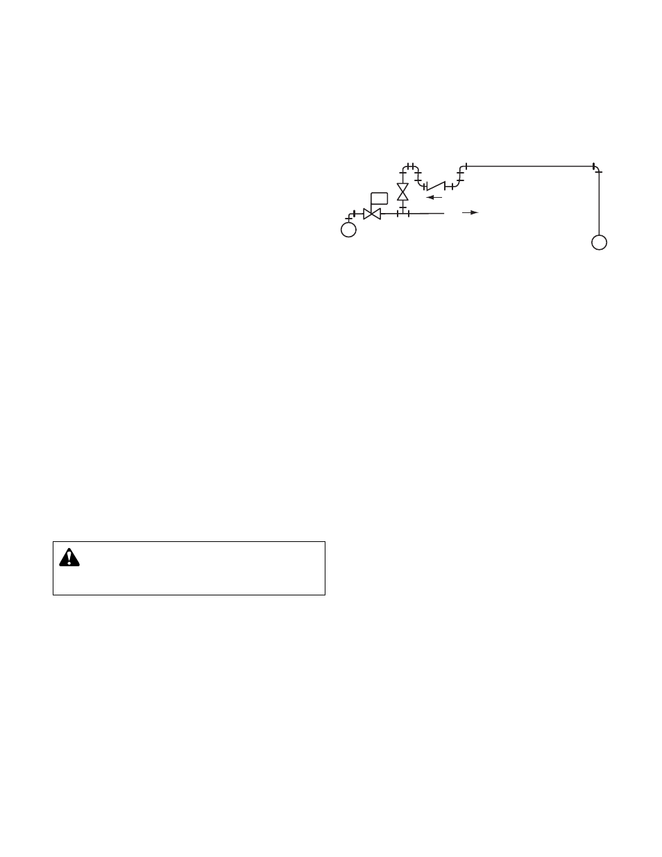
EQUALIZING LINE
A vacuum may be formed on radiation side of system when
steam stops flowing in mains. This vacuum may be higher than
return line vacuum, which would prevent condensate from
flowing back to pump. To correct this in an unzoned system,
install equalizer line as shown. To correct this in a zoned sys-
tem, install equalizer line for each zoned section or install a
vacuum breaker on supply line on radiation side of each zone
valve.
ACCUMULA
TOR TANK
An accumulator tank may be used to facilitate lifting conden
-
sate. The accumulator tank will be fitted with a float switch to
start the vacuum pump as accumulator fills. The vacuum pump
will then siphon condensate into the condensate receiver.
The vacuum sensor line in an accumulator tank system must
sense the vacuum in the accumulator tank as shown on the low
return piping diagrams. (Figure 9, page 5.)
3
ZONE CONTROL
VALVE
STEAM MAIN
M
TO ZONE
RETURN MAIN
W
ARNING: HIGH VOLTAGE ELECTRICITY
Disconnect and lock out power befor
e connecting or
servicing unit. Failure to follow these instructions could
result in serious injury or death.
FIG. 2 EQUALIZING CONNECTIONS FOR ZONED SYSTEMS