Sequence of opera tion – Bell & Gossett DN0136C Domestic Pump Vacuum Heating Units Series VCL User Manual
Page 4
SEQUENCE OF OPERA
TION
Ther
e are two separate and independent cycles of operation
in the VCD design – one of air evacuation and the other for
condensate return. This is accomplished by completely sep-
arating the air pumps from the condensate storage receiver
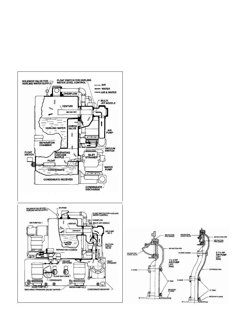
and water pumps. Fig 3 below illustrates a single, two com-
partment receiver, divided horizontally, where the air pumps
operate from the upper compartment or separation chamber
while the water pumps operate from the lower compartment
or condensate receiver. The unit below is similar except that
the air pump separation chamber and condensate receiver are
separate units, connected as shown in Figure 4. The operation
for both types of construction is identical.
AIR EV
ACUATION CYCLE
The independent air evacuation cycle begins when the vacuum
switch, responding to system requirements, starts the centrifu-
gal “air” pump. This pump circulates “hurling” water from the
separation chamber through the multi-jet nozzle, venturi and
returns it to the separation chamber. The water, forced at high
velocity across the gap between nozzle and venturi, entrains air
and gases in multiple jet streams, creating a smooth, steady
vacuum in the condensate receiver and system. The mixture is
discharged through the venturi into the separation chamber
where the air and gases separate from the “hurling” water and
are vented. When the desired vacuum has been produced in
the system, the vacuum switch stops the pump, and the check
valve at air inlet to separation chamber closes. preventing the
return of air to the system.
Replacement of the hurling water evaporated from the separa-
tion chamber is controlled by a solenoid valve connected to the
water supply and actuated by a float switch.
CONDENSA
TE RETURN CYCLE
The condensate r
eturn cycle begins when a float switch starts
a water pump on condensate rise. The condensate is pumped
into the boiler feed system until the preset low float switch set-
ting has been reached.
DUPLEX PUMPS
The second or lag pump of duplex water and/or air pumps
functions if the first or lead pump fails and automatically oper-
ates to double the capacity in the event of abnormal demand.
TEMPERA
TURE LIMIT SWITCH
Some units may be equipped with temperatur
e limit switches.
When located on the separation chamber, it is used to admit
cooling water if the hurling temperature exceeds a predeter-
mined limit.
A condition may be encountered where the temperature of the
condensate fluctuates intermittently to critically high levels,
where operation under vacuum could cause the condensate to
vaporize. A temperature limit switch can be installed on the
condensate receiver to prevent the air pump(s) from operating
where such a condition exists. Upon temperature drop the vac-
uum switch(es) will again control operation of the air pump(s).
V
ACUUM SWITCH ADJUSTMENTS
The vacuum switches ar
e adjusted and tested at the factory for
proper operation. The vacuum switch on the single unit and the
lead switch of the duplex unit is set to close at 3" Hg vacuum
and open at 8". The lag switch of a duplex unit is set to close
at 2" and open at 8".
These settings are suitable for all normal installations including
those having an accumulator tank or lift fitting when properly
piped. If settings must be readjusted, refer to manufacturer’s
instruction.
4
FIG. 4 100 & 150 VCD LIFT PIPE
ASSEMBLIES
FIG. 3
CUT-AWAY VIEW OF VCD PUMP WITH 50 VCD RECEIVER
25 VCD RECEIVERS ARE SIMILAR
CUT-AWAY VIEW OF VCD PUMP WITH 100 VCD
OR 150 VCD RECEIVERS